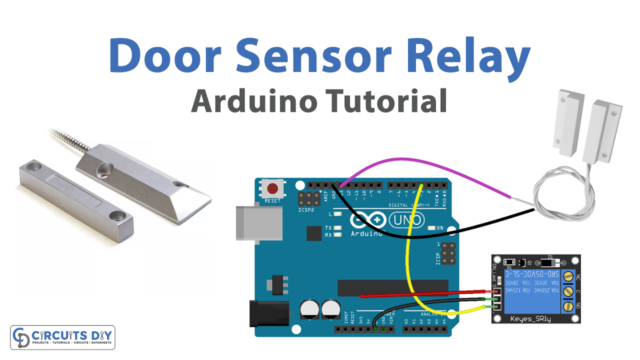
Introduction
A door sensor toggle LED is a program that turns on an LED light when a door sensor is activated and turns off the LED light when the door sensor is deactivated. The door sensor is connected to the Arduino UNO board, and the LED is connected to a digital output pin on the board. When the door sensor is triggered, it sends a signal to the Arduino, which causes the LED to turn on. When the door sensor is no longer triggered, the LED turns off.
The program is useful for creating interactive systems that respond to the opening and closing of a door, such as a security system or a home automation system. It can also be used for visual effects or as a way to indicate the status of a door.
Hardware Components
You will require the following hardware for Door Sensor with Arduino.
| S.no | Component | Value | Qty |
|---|---|---|---|
| 1. | Arduino UNO | – | 1 |
| 2. | USB Cable Type A to B | – | 1 |
| 3. | Door Sensor | – | 1 |
| 4. | 9V Power Adapter for Arduino | – | 1 |
| 5. | LED | – | 1 |
| 6. | Resistor | 220Ω | 1 |
| 7. | Breadboard | – | 1 |
| 8. | Jumper Wires | – | 1 |
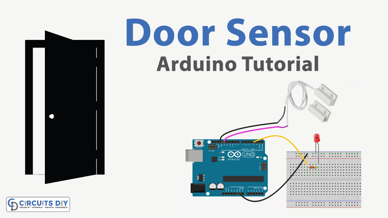
Door Sensor with Arduino
- Connect the LED to the breadboard. Connect the longer leg of the LED to a row on the breadboard, and the shorter leg to a different row.
- Connect the 220-ohm resistor to the breadboard. Connect one end of the resistor to the same row as the shorter leg of the LED, and the other end to a different row.
- Connect one end of a jumper wire to the row with the longer leg of the LED and the other end to a digital pin on the Arduino board.
- Connect the other end of the resistor to a ground pin on the Arduino board.
- Connect the door sensor to the breadboard. Connect one leg of the sensor to a row on the breadboard, and the other leg to a different row.
- Connect one end of a jumper wire to the row with one leg of the sensor and the other end to an input pin on the Arduino board.
- Connect the other end of the sensor to a power source on the breadboard (such as +5V or +3.3V).
- Open the Arduino software on your computer.
- Create a new sketch by clicking on “File” and then “New.”
- Set the pin mode for the digital pin that the LED is connected to by adding the following line of code at the beginning of the sketch:
pinMode(ledPin, OUTPUT);- Replace “ledPin” with the actual number of the digital pin that the LED is connected to.
- Set the pin mode for the input pin that the door sensor is connected to by adding the following line of code at the beginning of the sketch:
pinMode(sensorPin, INPUT);- Replace “sensorPin” with the actual number of the input pin that the sensor is connected to.
- In the loop function, add the following lines of code to read the state of the door sensor and turn the LED on or off accordingly:
int sensorState = digitalRead(sensorPin);digitalWrite(ledPin, sensorState);- Replace “sensorPin” and “ledPin” with the actual numbers of the input and output pins that the sensor and LED are connected to, respectively.
- Upload the sketch to the Arduino board by clicking the “Upload” button in the Arduino software.
Schematic
Make connections according to the circuit diagram given below.

Wiring / Connections
| Arduino | Sensor |
|---|---|
| D13 | VCC |
| GND | GND |
Installing Arduino IDE
First, you need to install Arduino IDE Software from its official website Arduino. Here is a simple step-by-step guide on “How to install Arduino IDE“.
Code
Now copy the following code and upload it to Arduino IDE Software.
const int DOOR_SENSOR_PIN = 13; // Arduino pin connected to door sensor's pin
const int LED_PIN         = 3;  // Arduino pin connected to LED's pin

// variables will change:
int ledState = LOW;   // the current state of LED
int lastDoorState;    // the previous state of door sensor
int currentDoorState; // the current state of door sensor

void setup() {
  Serial.begin(9600);                     // initialize serial
  pinMode(DOOR_SENSOR_PIN, INPUT_PULLUP); // set arduino pin to input pull-up mode
  pinMode(LED_PIN, OUTPUT);               // set arduino pin to output mode

  currentDoorState = digitalRead(DOOR_SENSOR_PIN);
}

void loop() {
  lastDoorState    = currentDoorState;             // save the last state
  currentDoorState = digitalRead(DOOR_SENSOR_PIN); // read new state

  if (lastDoorState == HIGH && currentDoorState == LOW) { // state change: HIGH -> LOW
    Serial.println("The door-closing event is detected");

    // toggle state of LED
    ledState = !ledState;

    // control LED arccoding to the toggled state
    digitalWrite(LED_PIN, ledState);
  }
}
Working Explanation
The working of this kind of program is very simple. In the setup function, the program sets the pin mode for the digital pin that the LED is connected to as “OUTPUT,” and the pin mode for the input pin that the door sensor is connected to as “INPUT.”
In the loop function, the program reads the state of the door sensor using the digitalRead function. The digitalRead function returns a value of HIGH or LOW depending on the state of the sensor. If the sensor is triggered (for example, if a door is opened), the digitalRead function returns HIGH. If the sensor is not triggered (for example, if a door is closed), the function returns LOW.
The program then uses the digitalWrite function to turn the LED on or off based on the state of the door sensor. If the digitalRead function returns HIGH, the digitalWrite function turns the LED on. If the digitalRead function returns LOW, the digitalWrite function turns the LED off.
Applications
- Security systems
- Home automation
- Interactive displays
- Timing applications
Conclusion.
We hope you have found this Door Sensor Circuit very useful. If you feel any difficulty in making it feel free to ask anything in the comment section.