Introduction
To understand the concept of accelerometer and gyroscope, take the example of your smartphone. While watching the video, when you change the direction of your phone, the phone automatically changes from portrait to landscape mode. This happens because of the accelerometer in your phone. In the same vein, when you play games on your mobile phones, in some games the GPS helps you to navigate. That is because of the gyroscope present in smartphones. In short, to measure the acceleration of the moving body or to measure the angular velocity of any object accelerometer and gyroscope are effectively used respectively. Hence In this tutorial, we are going to interface “MPU6050 Accelerometer and Gyroscope Sensor with Arduino UNO”.
How does an Accelerometer work?
The accelerometer measures the vibration of any object. Practically, the vibrations of any object cause the piezoelectric effect. Thus, the piezoresistive and piezo capacitive elements convert these mechanical motions into an electrical signal. In other words, an accelerometer converts mechanical energy into electrical energy.
How Gyroscope Works?
A gyroscope is used to measure the rotation of any particular axis. It consists of the drive arm which is attached to the sensing element. The arm creates the motion in the sensing element which produces the angular velocity. This angular velocity is then converted into electrical signals. Hence MEMS gyroscope sensors detect and estimate the motion of the objects. Thus, measure the rate of rotation around the 3 axes. The demand for these MEMS sensors is increasing day by day because of their use in mobile phones and other gaming applications.
Hardware Required
| S.no | Component | Value | Qty |
|---|---|---|---|
| 1. | Arduino | UNO | 1 |
| 2. | USB Cable Type A to B | – | 1 |
| 3. | Jumper Wires | – | – |
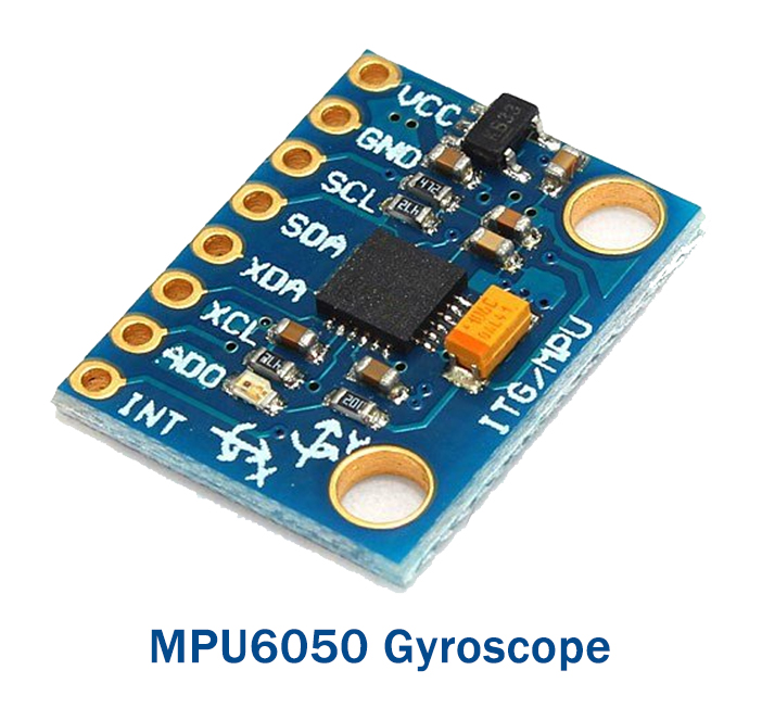
| 4. | Accelerometer Gyroscope Sensor | MPU6050 | 1 |
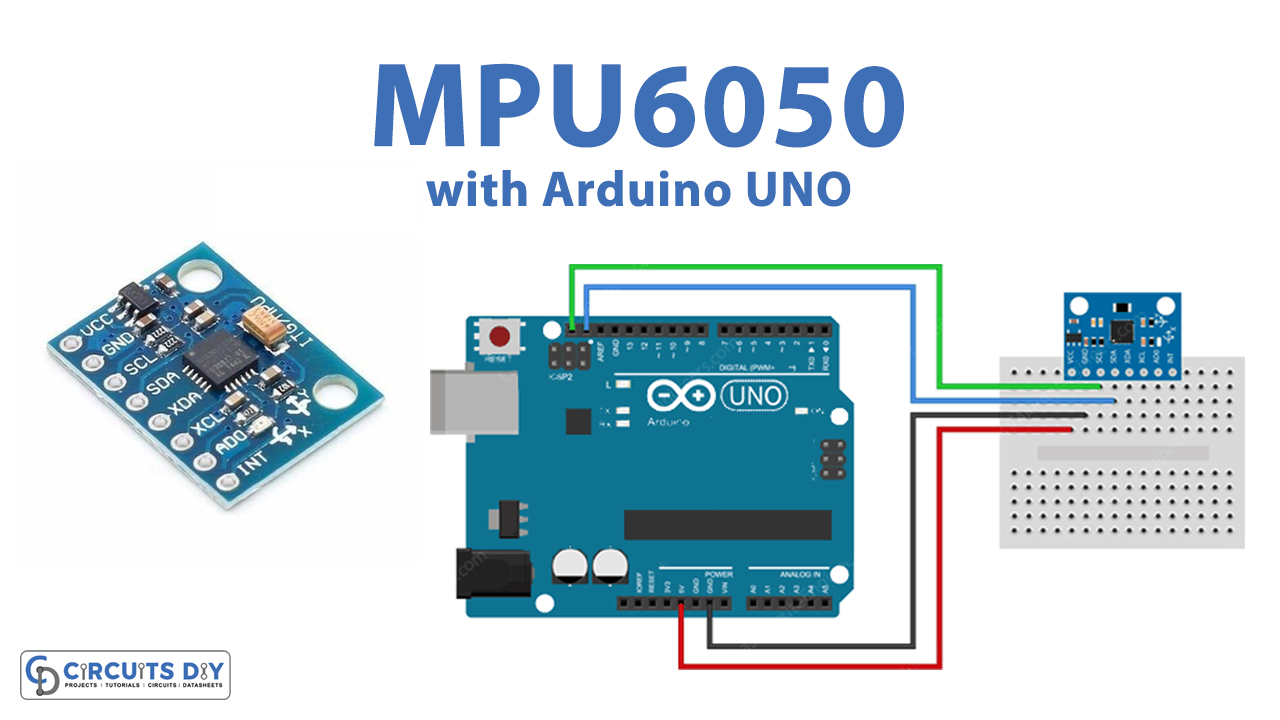
Circuit Diagram

Connection Table
| Arduino | MPU6050 Accelerometer Gyroscope Sensor |
|---|---|
| 5V | VCC |
| GND | GND |
| A5 | SCL |
| A4 | SDA |
Arduino Code – Reading Accelerometer, Gyroscope and Temperature Data
#include <Adafruit_MPU6050.h>
#include <Adafruit_Sensor.h>
#include <Wire.h>

Adafruit_MPU6050 mpu;

void setup(void) {
	Serial.begin(115200);

	// Try to initialize!
	if (!mpu.begin()) {
		Serial.println("Failed to find MPU6050 chip");
		while (1) {
		  delay(10);
		}
	}
	Serial.println("MPU6050 Found!");

	// set accelerometer range to +-8G
	mpu.setAccelerometerRange(MPU6050_RANGE_8_G);

	// set gyro range to +- 500 deg/s
	mpu.setGyroRange(MPU6050_RANGE_500_DEG);

	// set filter bandwidth to 21 Hz
	mpu.setFilterBandwidth(MPU6050_BAND_21_HZ);

	delay(100);
}

void loop() {
	/* Get new sensor events with the readings */
	sensors_event_t a, g, temp;
	mpu.getEvent(&a, &g, &temp);

	/* Print out the values */
	Serial.print("Acceleration X: ");
	Serial.print(a.acceleration.x);
	Serial.print(", Y: ");
	Serial.print(a.acceleration.y);
	Serial.print(", Z: ");
	Serial.print(a.acceleration.z);
	Serial.println(" m/s^2");

	Serial.print("Rotation X: ");
	Serial.print(g.gyro.x);
	Serial.print(", Y: ");
	Serial.print(g.gyro.y);
	Serial.print(", Z: ");
	Serial.print(g.gyro.z);
	Serial.println(" rad/s");

	Serial.print("Temperature: ");
	Serial.print(temp.temperature);
	Serial.println(" degC");

	Serial.println("");
	delay(500);
}
Working Explanation
Interface MPU6050 Accelerometer and Gyroscope Sensor with Arduino UNO according to the circuit diagram. Open Arduino IDE. Copy the above code and paste it there. Now, upload it to your Arduino UNO. Open the serial monitor. You can see the readings on the serial monitor. Change the directions of the module sensor to observe the different readings.
Code Explanation
- To start the coding, first you need the required libraries of Adafruit_MPU6050 and Adafruit_Sensor. You can download the libraries from:
https://github.com/adafruit/Adafruit_MPU6050
- Now, include those libraries. Also, include the wire library to communicate with the external 12C device. Now create Adafruit_MPU6050 to access related functions.
- In the void setup, use the begin functions to initialize the serial communication and to check if the chip is correct. Use the setAccelerometerRange( ) to set the accelerometer range. Remember that, the smaller range would provide the more sensitive readings. In the same vein, set the gyroscope range by using setGyroRange( ). Similarly, set the bandwidth by using the setFilterBandwidth( ).
- In the void loop, create the object sensors_event_t to hold the results. To read a new value from the sensor and to convert those values in the SI unit and scale the values, call getEvent. In the end, use print and println functions to print the values on the Serial monitor.
Application and Uses
- It can be used in Robotics applications.
- Further, in the tilt sensing devices.
- Moreover, in gaming devices.
- Also, for IMU measurements.