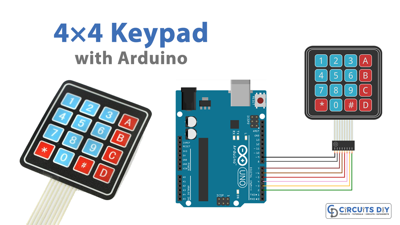
The 4×4 matrix keypad is an input device, it is usually used to provide input value in a project. It has 16 keys in total, which means it can provide 16 input values. The most interesting thing is it used only 8 GPIO pins of a microcontroller. These Keypad modules are made of thin, flexible membrane material. To construct this keypad you need sixteen push buttons and skills to make rows and columns between switches. Nowadays we can get ready-made keypads, in this keypad, eight female connectors are placed to interface with other circuits, pins 1 – 4 are rows, and pins 5 – 8 are columns. Many electronics projects need this keypad, here in this tutorial we are going to interface a 4×4 Keypad with Arduino.
In our case, we connect a 4 x 4 keypad with Arduino and the sketch code helps to view the pressed key from the keypad through the serial monitor.
Hardware Required
| S.No | Components | Value | Qty |
|---|---|---|---|
| 1 | Arduino Uno | – | 1 |
| 2 | Keypad | 4×4 | 1 |
| 3 | Connecting Wires | – | – |
4×4 Keypad Pinout

Arduino Hookup

Working Explanation
To receive data from 12 buttons, we need to use 12 digital pins from our Arduino. But using the keypad, we only need 7 digital pins. Keypad pins are divided into two groups: row and column. When a switch/key is pressed, the corresponding row and column will get short. The output of the corresponding column goes to go low. Since we have made all the rows zero so this gives the column number of the pressed key. After the detection of the column number, the controller set’s all the rows to high. Each row is one by one set to zero by the Arduino and the earlier detected column is checked and obviously, it becomes zero. The row due to which the column gets zero is the row number of the pressed key.
Arduino 4×4 Keypad Sketch Code
#include <Keypad.h>

const byte numRows= 4; //number of rows on the keypad
const byte numCols= 4; //number of columns on the keypad

After uploading the code, open the serial monitor and press each of the keypad buttons. You should see the number corresponding to each button.

//keymap defines the key pressed according to the row and columns just as appears on the keypad
char keymap[numRows][numCols]=
{
{‘1’, ‘2’, ‘3’, ‘A’},
{‘4’, ‘5’, ‘6’, ‘B’},
{‘7’, ‘8’, ‘9’, ‘C’},
{‘*’, ‘0’, ‘#’, ‘D’}
};

//Code that shows the keypad connections to the Arduino terminals
byte rowPins[numRows] = {9,8,7,6}; //Rows 0 to 3
byte colPins[numCols]= {5,4,3,2}; //Columns 0 to 3

//initializes an instance of the Keypad class
Keypad myKeypad= Keypad(makeKeymap(keymap), rowPins, colPins, numRows, numCols);

void setup()
{
Serial.begin(9600);
}

//If the key is pressed, this key is stored in the ‘key pressed’ variable
//If the key is not equal to ‘NO_KEY’, then this key is printed out
//if count=17, then count is reset back to 0 (this means no key is pressed during the whole keypad scan process
void loop()
{
char keypressed = myKeypad.getKey();
if (keypressed != NO_KEY)
{
Serial.print(keypressed);
}
}
Related posts:
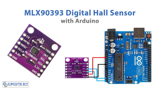 Interface MLX90393 Digital Hall Sensor Module with Arduino
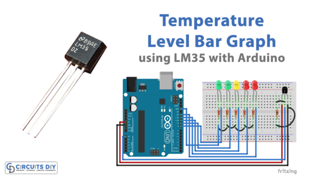 Temperature Level Bar Graph using LM35 with Arduino
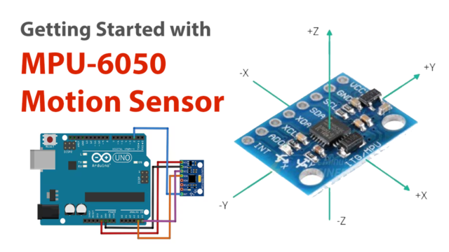 Getting Started with MPU-6050 IMU (6 DOF) Motion Sensor
 How Soil Moisture Sensor Works and Interface it with Arduino UNO
 Interfacing TTP229 16 Key Capacitive Touch Keypad with Arduino
 DS1307 RTC Module - Arduino Tutorial