Introduction
This blog post will delve into the Interfacing H3V4F 433MHz RF Receiver Module with Arduino to create a whole new world of communication possibilities.
Imagine the endless possibilities of sending and receiving data wirelessly using radio frequencies. From remotely controlling your home automation system to receiving real-time updates from your weather station, the H3V4F 433MHz RF Receiver Module can open up a world of possibilities.
Are you ready to join us on this journey and learn how to interface the H3V4F 433MHz RF Receiver Module with an Arduino microcontroller? Let’s get started!
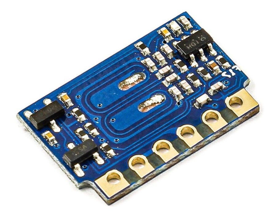
What is the H3V4F 433MHz RF Receiver Module?
The H3V4F 433MHz RF receiver module is a device that we can use to receive and decode signals from wireless remote controls that operate at 433MHz frequency. It is typically used in projects requiring wireless communication, such as home automation systems, security systems, and remote control devices.
Hardware Components
You will require the following hardware for Interfacing the H3V4F 433MHz RF Receiver Module with Arduino.
| S.no | Component | Value | Qty |
|---|---|---|---|
| 1. | Arduino UNO | – | 1 |
| 2. | Wireless Receiver Module | H3V4F | 1 |
| 3. | Breadboard | – | 1 |
| 4. | Jumper Wires | – | 1 |
H3V4F 433MHz RF Receiver Module with Arduino
Now that you have a complete understanding of the RF receiver module, you need to follow the given steps in order to interface it with Arduino.
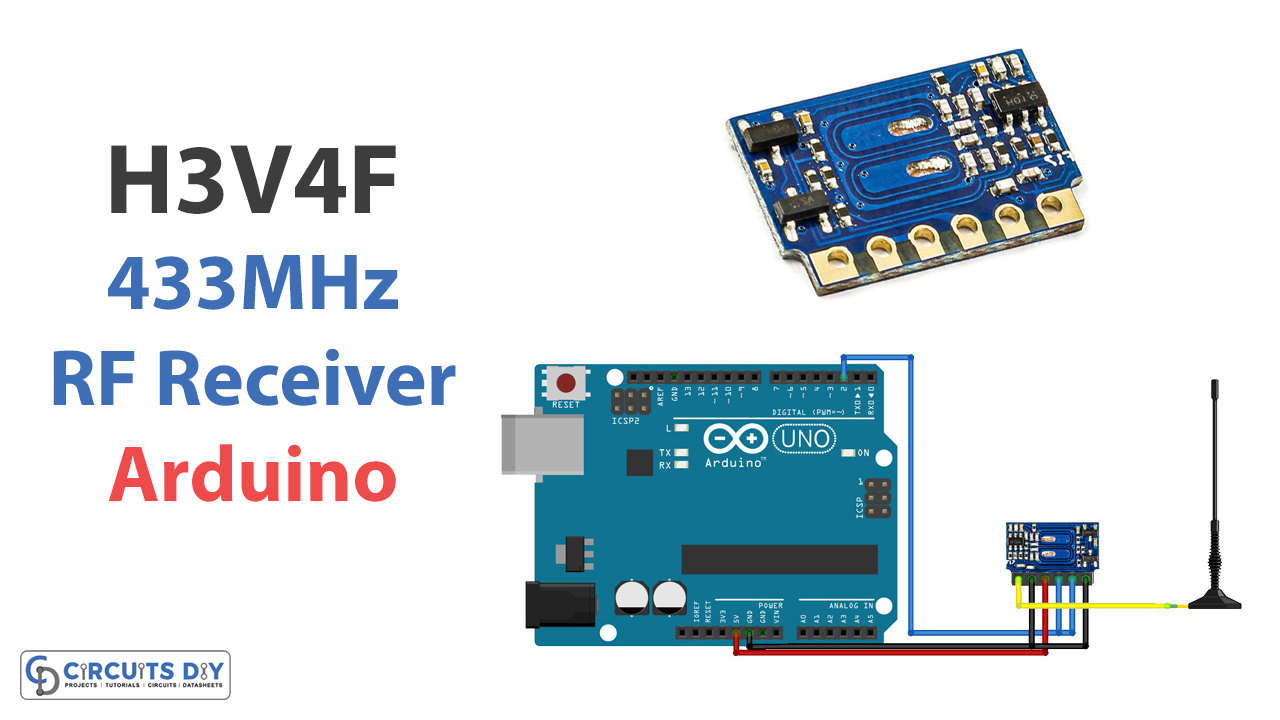
Schematic
Make connections according to the circuit diagram given below.
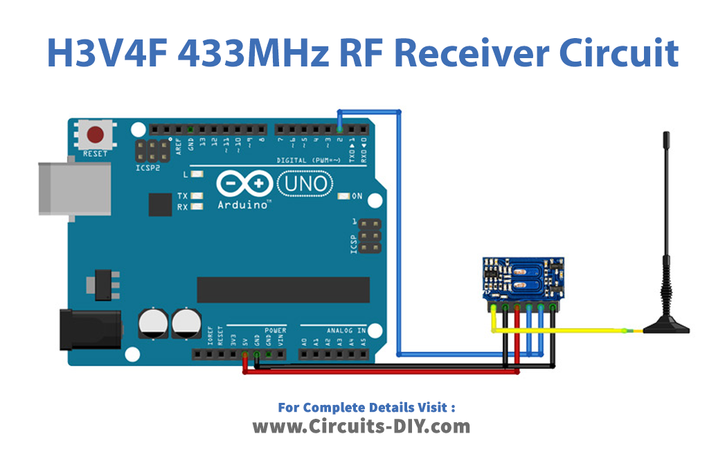
Wiring / Connections
| Arduino | Receiver Module |
|---|---|
| 5V | VCC |
| GND | GND |
| D2 | DATA |
Installing Arduino IDE
First, you need to install Arduino IDE Software from its official website Arduino. Here is a simple step-by-step guide on “How to install Arduino IDE“.
Installing Libraries
Before you start uploading a code, download and unzip the following libraries at /Progam Files(x86)/Arduino/Libraries (default), in order to use the sensor with the Arduino board. Here is a simple step-by-step guide on “How to Add Libraries in Arduino IDE“.
Code
Now copy the following code and upload it to Arduino IDE Software.
/*
  Simple example for receiving

  https://github.com/sui77/rc-switch/
*/

#include <RCSwitch.h>

RCSwitch mySwitch = RCSwitch();

void setup() {
  Serial.begin(9600);
  mySwitch.enableReceive(0);  // Receiver on interrupt 0 => that is pin #2
}

void loop() {
  if (mySwitch.available()) {

    int value = mySwitch.getReceivedValue();

    if (value == 0) {
      Serial.print("Unknown encoding");
    } else {
      Serial.print("Received ");
      Serial.print( mySwitch.getReceivedValue() );
      Serial.print(" / ");
      Serial.print( mySwitch.getReceivedBitlength() );
      Serial.print("bit ");
      Serial.print("Protocol: ");
      Serial.println( mySwitch.getReceivedProtocol() );
    }

    mySwitch.resetAvailable();
  }
}
Let’s Test It
We must now put the circuit to the test. Once the code is uploaded to the Arduino board, it will test the radio connection. Transmitted data can be seen by the receiver via the Serial monitor!
Working Explanation
- The above-given code uses the RCSwitch library to receive data transmitted using radio frequency (RF) signals. The RCSwitch library is a convenient way to interface with RF receiver modules like the H3V4F 433MHz RF Receiver Module.
- In the void setup, the serial monitor is initialized, and the RCSwitch object is configured to listen for incoming RF signals on interrupt 0, which corresponds to pin #2 on the Arduino.
- In the void loop function, the program continuously checks for the availability of incoming RF signals using the available() function. If a signal is available, the getReceivedValue() function is used to retrieve the decoded value of the signal, and the getReceivedBitlength() and getReceivedProtocol() functions are used to get the length of the signal in bits and the protocol used to encode the signal, respectively. The received data is then printed to the serial monitor using the Serial.println() function.
- After that, the resetAvailable() function is called to reset the availability flag and prepare the RCSwitch object for the next incoming signal.
Applications
- Wireless control network
- Remote control devices
- Wireless data transmission systems, etc
Conclusion.
We hope you have found this Interfacing H3V4F 433MHz RF Receiver Module with Arduino Circuit very useful. If you feel any difficulty in making it feel free to ask anything in the comment section.