Introduction
Thunderstorms are an awe-inspiring phenomenon that can both captivate and terrify us. The rumble of thunder and the bright flashes of lightning remind us of the immense power of nature. But have you ever wondered just how far away a thunderstorm actually is? Perhaps you’ve felt a sense of unease as you watched lightning strikes in the distance, wondering if they were getting closer. If so, you’ll be excited to learn about an electronic circuit that can help you measure the distance of a thunderstorm with surprising accuracy.
In this blog post, we’ll explore how this circuit works and how you can use it to get an advanced warning of a thunderstorm’s approach. So, grab a cup of coffee, sit back, and let’s dive into this new tutorial.
Overview
Calculating the Distance of Thunderstorms Light travels at a speed of 300,000 m/s, while sound waves travel at 333 m/s in the atmosphere, depending on the ambient temperature. This is the reason why thunder is heard after a short delay following the lightning flash. We can use the delay between lightning and thunder to calculate the distance of the thunderstorm from the observer. For every 3 seconds that elapse between the lightning and thunder, the thunderstorm is 1 kilometer away. This is equivalent to 0.3 seconds for every 100 meters. The electronic circuit described below puts this theoretical knowledge into practice.
Hardware Required
| S no | Components | Value | Qty |
|---|---|---|---|
| 1 | IC | 555, 4017 | 1, 2 |
| 2 | Polar Capacitor | 10u 10V | 1 |
| 3 | Resistor | 47k, 270k, 220k, 270 | 2, 1, 1, 2 |
| 4 | V. Resistor | 500k | 1 |
| 5 | Switch | – | 3 |
| 6 | Battery | 9V | 1 |
| 7 | LEDs | – | 18 |
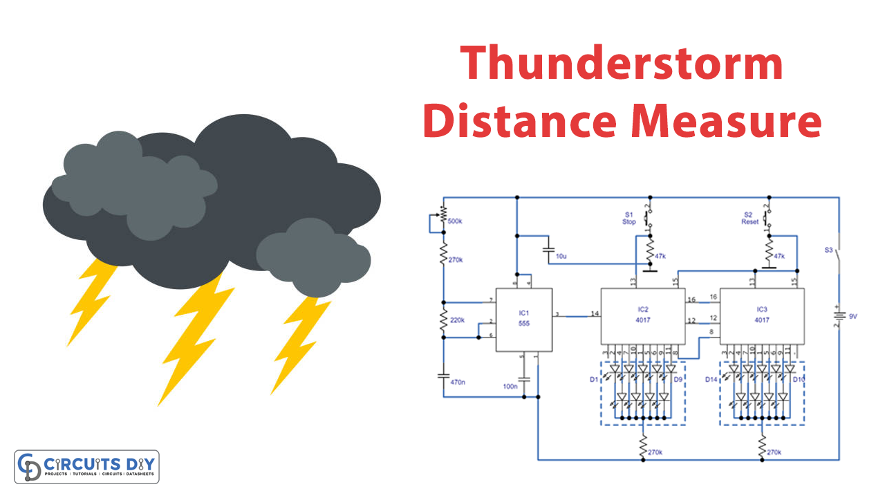
Circuit Diagram
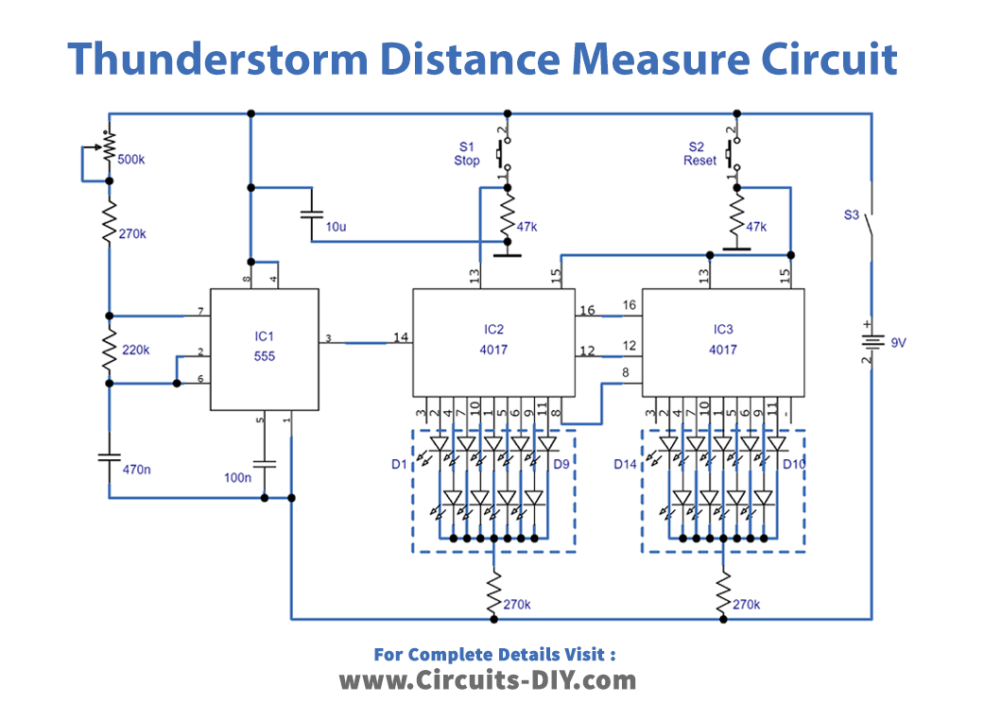
Working Explanation
The circuit is based on a 555 timer IC, which functions as an astable multivibrator with a frequency of 3.33 Hz and a time scale of 0.3 s. This time scale is equivalent to the time difference between lightning and thunder. When the lightning flash is observed, the circuit is activated by pressing pushbutton S2. Counters IC2 and IC3, connected in series, are reset to zero by a reset signal. The clock input of IC2 is connected to the output signal of IC1, which is then processed by IC2.
The LED D1 lights up after 0.3 s, and each subsequent clock pulse triggers a higher output after 0.3 s. The counting process is stopped by pressing pushbutton S1 when the thunder is audible. One or two LEDs then display the distance of the thunderstorm from the observer across D1…D18.
Counter IC2 counts the distance from 100 m to 900 m. If the thunderstorm is beyond that distance, counter IC3 counts the kilometers. For example, if only LED D5 lights up, the thunderstorm is 500 m away. If LEDs D16 and D3 light up, the distance is 7300 m, and the maximum distance that can be measured is 10 km.
The circuit consumes a maximum current of 30 mA and can be powered by a 9 V battery. An electronic watch with a chronograph feature can synchronize the circuit. The potentiometer P1 can be adjusted so that LED D18 lights up 27 seconds after S2 is released (the stopwatch must be started at the same time).
Additional features that you can add to the thunderstorm distance counter circuit include an LDR (Light Dependent Resistor). This triggers the counter automatically when lightning strikes and a microphone that stops the counting process automatically when the thunder is audible. However, the LDR may be effective only at night.
Final Words
In conclusion, an electronic circuit can measure the distance of thunderstorms by calculating the time difference between lightning and thunder. The circuit described in this article is based on a 555 timer IC and can measure thunderstorm distances up to 10 km. The circuit is easy to use and consumes low power, making it a useful tool for measuring the distance of thunderstorms. Try this circuit, and for any query, feel free to ask in the comment section.