Introduction
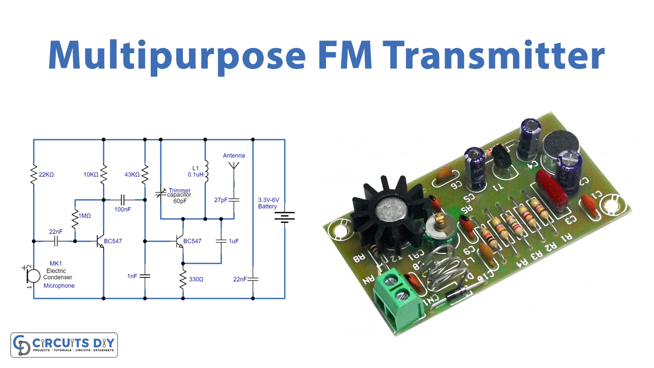
Knowledge matures when practically gets implemented. It allows a person to get a clear sense of many things. So, to understand the process of frequency modulation we are here with the interesting project of a Simple FM Transmitter by using two transistors. Hence, the circuit works effectively in the distant or close range. As you already know that there are different ways to transmit data. Thus, in frequency modulation, the data is transferred by varying the frequency of carrier waves. Also, there are different ways to make this circuit. Thus, we are making it by using the two transistors FM transmitter. The circuit also requires very few external components which ultimately makes it affordable. So, In this tutorial, we are going to “multipurpose FM transmitter circuit”.
Hardware Required
| S.no | Component | Value | Qty |
|---|---|---|---|
| 1. | Transistor | BC547 | 2 |
| 2. | Electret microphone Condenser | – | 1 |
| 3. | Inductor | 0.1μH | 1 |
| 4. | Trim Capacitor | 60pF | 1 |
| 5. | Capacitors | 22nF, 100nF, 1nF, 1μF, 27pF, 22nF | 2, 1, 1, 1, 1, 1 |
| 6. | Resistor | 22KΩ, 1MΩ, 10KΩ, 43KΩ, 330Ω | 1, 1, 1, 1, 1 |
| 7. | Battery | 3.3v-6v | 1 |
| 8. | Antenna | – | 1 |
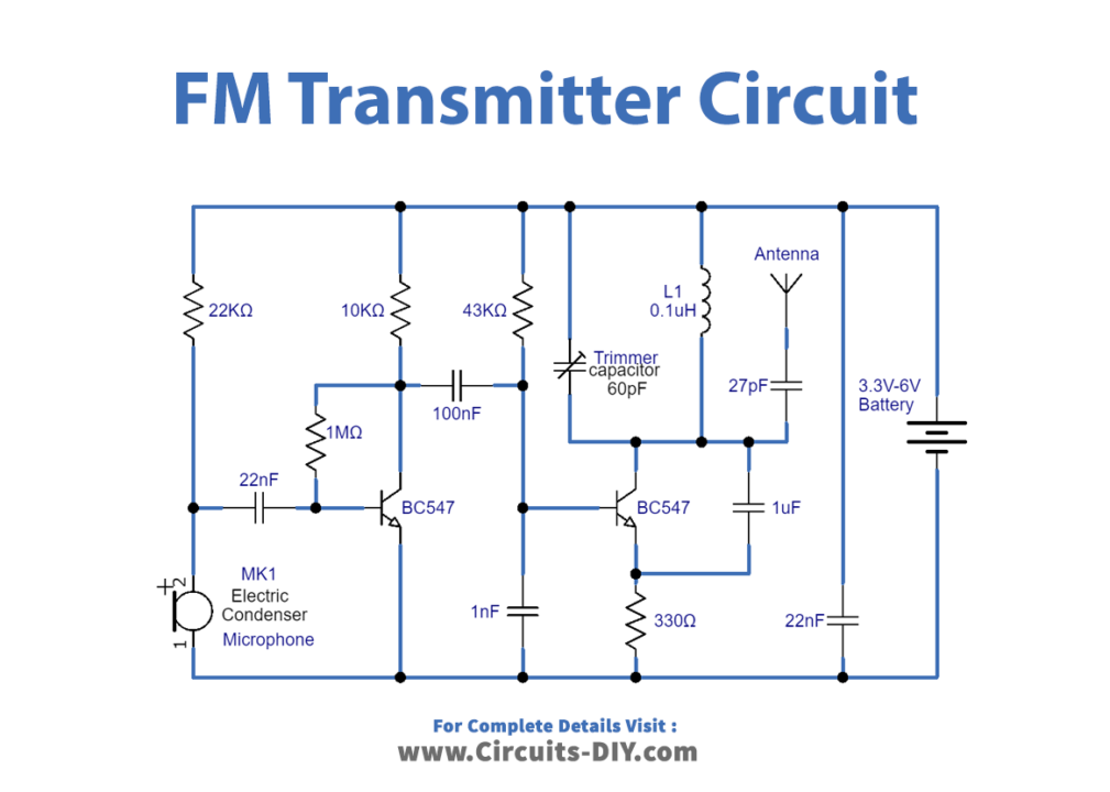
Circuit Diagram
Working Explanation
To make the Multipurpose FM transmitter circuit we are using the condenser microphone that provides the audio signal. When the audio signal is from the microphone, it converts the signal into an electrical signal and then that signal penetrates at the base of the first NPN transistor which increases the amplitude of the signal. The signal gets more amplified by the NPN transistor Q2. To generate the carrier waves, we have created the tank circuit using a capacitor and inductor. Here we are using the variable capacitor which changes the resonant frequency for fine modification. We connect the antenna to send the carrier waves. Now you can hear the audio signal given to this circuit on any of the radios in close range.
Application and Uses
- For FM radios,
- Toys.
- In different industries.