The four-level temperature-controlled switch circuit distinguishes between different temperature levels. After that, the circuit switches ON/OFF the relays according to the temperature detected. The project involves the IC LM324 as its main component and also, and relays, potentiometer, and transistor are part of the circuit.
Hardware Required
| S.no | Component | Value | Qty |
|---|---|---|---|
| 1. | DC Battery | 5V-12V | 1 |
| 2. | Thermistor | 10KΩ | 1 |
| 3. | IC | LM324 | 4 |
| 4. | Variable Resistor | 10KΩ | 4 |
| 5. | Resistors | 1KΩ, 10KΩ | 4,1 |
| 6. | PNP Transistor | 2N3906 | 4 |
| 7. | Relay | 12v | 4 |
| 8. | Diode | 1N4007 | 4 |
IC LM324
It is a 14-dip low-cost, quad-operational amplifier.

| PIN No | Label | Description |
|---|---|---|
| 1 | Output 1 | Operational amplifier 1 output |
| 2 | – Input 1 | Inverting input of operational amplifier 1 |
| 3 | + Input 1 | Non-Inverting input of operational amplifier 1 |
| 4 | Vcc | Positive supply |
| 5 | + Input 2 | Non-Inverting input of operational amplifier 2 |
| 6 | – Input 2 | Inverting input of operational amplifier 2 |
| 7 | Output 2 | Operational amplifier 2 output |
| 8 | Output 3 | Operational amplifier 3 output |
| 9 | – Input 3 | Inverting input of operational amplifier 3 |
| 10 | + Input 3 | Non-Inverting input of operational amplifier 3 |
| 11 | Gnd | Negative supply |
| 12 | + Input 4 | Non-Inverting input of operational amplifier 4 |
| 13 | – Input 4 | Inverting input of operational amplifier 4 |
| 14 | Output 4 | Operational amplifier 4 output |
Features
- Low current drain
- Wide range of power Supply: 3V to 32V
- Integration of four operational amplifiers in a single package
- Operating temperature: 0°C to 70°C
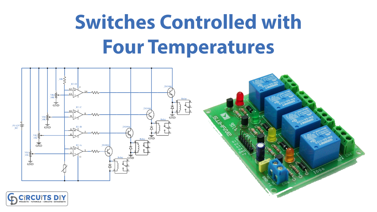
Circuit Diagram
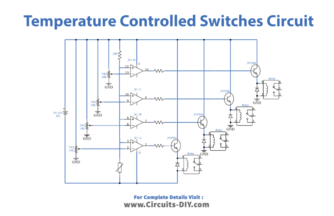
Circuit Explanation
IC LM324 has built-in four independent operational amplifiers. Moreover, this circuit involves the functioning of all four operational amplifiers of the IC LM324 but each using a separate IC. Furthermore, with the adjustment of the 10KΩ variable resistor attached to each of the IC, four temperature levels are set. Also, the resistor of value 680Ω is to limit the current flowing through LEDs.
Works in such that the thermistor detects the temperature in the surrounding/room and, thus, sends a signal to all four ICs. All four ICs are working in comparator mode. Hence, all four ICs amplify and compare the signal with its pre-set variable resistor value. After that, the IC with its Output HIGH signal activates its corresponding relay. Meanwhile, the corresponding transistor amplifies the weak signal to be sent to the relay. Thus, the electronic circuit or any device connected to the relay activates. Moreover, diode 1N4007 prevents back emf in the circuit.
Additionally, the relay ratings selected should be that of the battery voltage.