Introduction
Picture this, a small yet powerful display module, capable of displaying stunning images and animations in rich, full color. The 0.96 Inch SPI OLED Full Color IPS Display Module is a compact and versatile display module that packs a punch. With its high resolution, fast refresh rate, and wide viewing angle, this module is the perfect choice for creating dynamic user interfaces and bringing your projects to life.
Whether you’re working on an IoT project, a wearable device, or an embedded system, the 0.96-inch SPI OLED Full Color IPS Display Module is the perfect addition. It’s small and easy to connect to an Arduino microcontroller, which makes it a powerful tool that can be used in any project. The possibilities are endless, from displaying real-time data to creating interactive interfaces. So, if you’re ready to add some visual flair to your next project, the 0.96 Inch SPI OLED Full Color IPS Display Module is a perfect choice.
What is OLED Display Module?
A form of flat-panel display known as an organic light-emitting diode, or OLED, display module, employs the utilization of organic materials in order to manufacture the pixels that comprise the picture. Because of their high contrast, broad viewing angles, and rapid reaction times, these screens are ideal for usage in a variety of devices, such as smartphones, TVs, and computer monitors.
Hardware Components
You will require the following hardware for Interfacing 0.96 Inch SPI OLED Full Color IPS Display Module with Arduino.
| S.no | Component | Value | Qty |
|---|---|---|---|
| 1. | Arduino UNO | – | 1 |
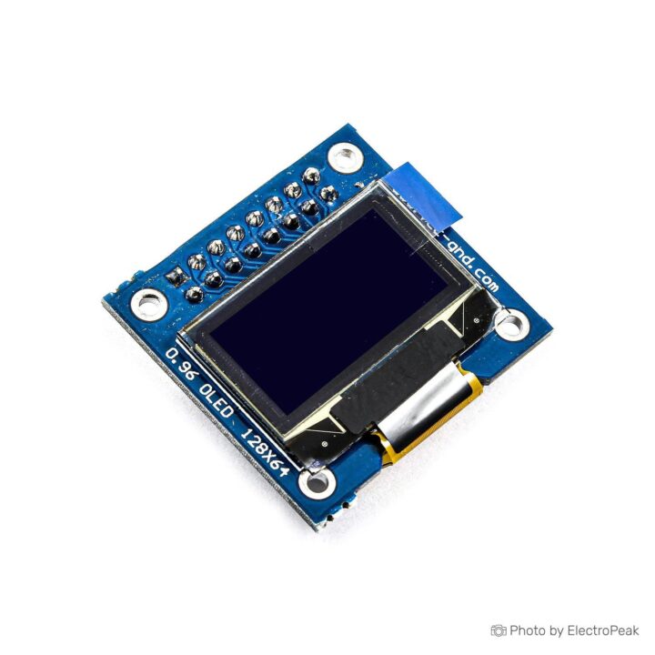
| 2. | 0.96 inch OLED Display Module | 80×160 | 1 |
| 3. | Breadboard | – | 1 |
| 4. | Jumper Wires | – | 1 |
0.96 Inch OLED with Arduino
Now to interface OLED Full Color IPS Display Module with Arduino you need to follow the given steps:
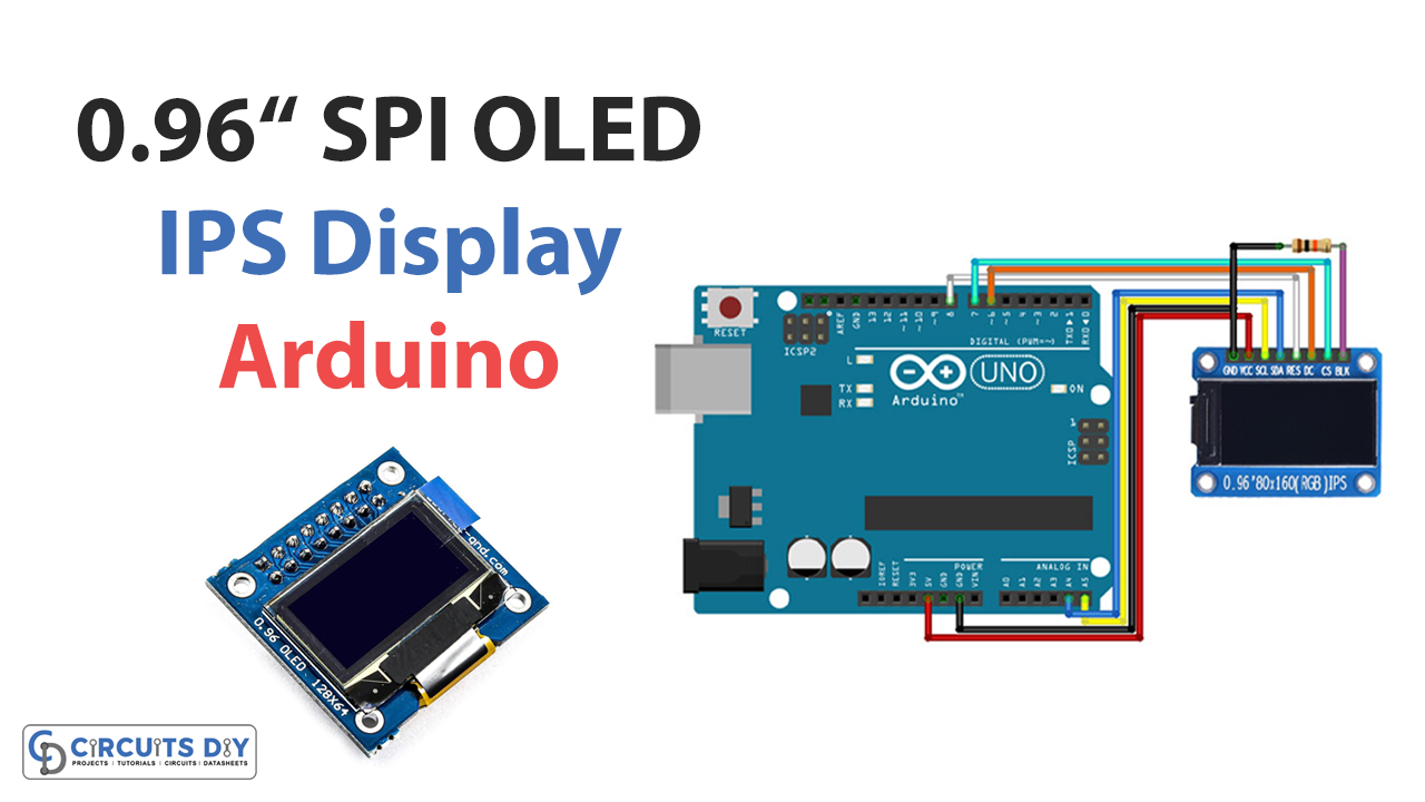
Schematic
Make connections according to the circuit diagram given below.
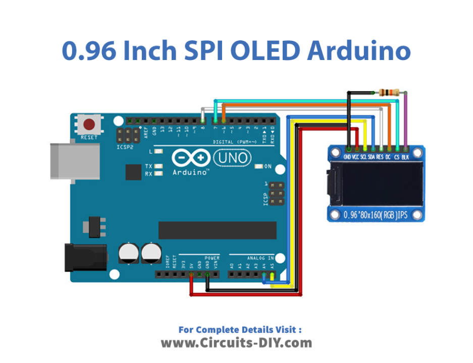
Wiring / Connections
| Arduino | OLED Display |
|---|---|
| 5V | VCC |
| GND | GND |
| A4 | SDA |
| A5 | SCL |
| D6 | DC |
| D7 | CS |
| D8 | RES |
Installing Arduino IDE
First, you need to install Arduino IDE Software from its official website Arduino. Here is a simple step-by-step guide on “How to install Arduino IDE“.
Installing Libraries
Before you start uploading a code, download and unzip the following libraries at /Progam Files(x86)/Arduino/Libraries (default), in order to use the sensor with the Arduino board. Here is a simple step-by-step guide on “How to Add Libraries in Arduino IDE“.
Code
Now copy the following code and upload it to Arduino IDE Software.
  /*
  modified on Des 13, 2020
  Modified by MohammedDamirchi from https://github.com/adafruit/Adafruit-ST7735-Library
  Home
*/

/***************************************************
This is a library for the Adafruit 1.8" SPI display.

This library works with the Adafruit 1.8" TFT Breakout w/SD card
  ----> http://www.adafruit.com/products/358
The 1.8" TFT shield
  ----> https://www.adafruit.com/product/802
The 1.44" TFT breakout
  ----> https://www.adafruit.com/product/2088
as well as Adafruit raw 1.8" TFT display
  ----> http://www.adafruit.com/products/618

  Check out the links above for our tutorials and wiring diagrams
  These displays use SPI to communicate, 4 or 5 pins are required to
  interface (RST is optional)
  Adafruit invests time and resources providing this open source code,
  please support Adafruit and open-source hardware by purchasing
products from Adafruit!

Written by Limor Fried and Ladyada for Adafruit Industries.
  MIT license, all text above must be included in any redistribution
 ****************************************************/

#include <Adafruit_GFX.h>    // Core graphics library
#include <Adafruit_ST7735.h> // Hardware-specific library
#include <SPI.h>


// For the breakout, you can use any 2 or 3 pins
// These pins will also work for the 1.8" TFT shield
#define TFT_CS     10
#define TFT_RST 9 // you can also connect this to the Arduino reset
In which case, set this #define pin to -1!
#define TFT_DC     8

// Option 1 (recommended): must use the hardware SPI pins
// (for UNO thats sclk = 13 and sid = 11) and pin 10 must be
an output. This is much faster - also required if you want
// to use the microSD card (see the image drawing example)
Adafruit_ST7735 tft = Adafruit_ST7735(TFT_CS,  TFT_DC, TFT_RST);

Option 2: use any pins, but a little slower!
#define TFT_SCLK 13 // set these to be whatever pins you like!
#define TFT_MOSI 11 // set these to be whatever pins you like!
//Adafruit_ST7735 tft = Adafruit_ST7735(TFT_CS, TFT_DC, TFT_MOSI, TFT_SCLK, TFT_RST);


float p = 3.1415926;

void setup(void) {
  Serial.begin(9600);
  Serial.print("Hello! ST7735 TFT Test");

  // Use this initializer if you're using a 1.8" TFT
//  tft.initR(INITR_BLACKTAB);   // initialize a ST7735S chip, black tab

  // Use this initializer (uncomment) if you're using a 1.44" TFT
  //tft.initR(INITR_144GREENTAB);   // initialize a ST7735S chip, black tab

  // Use this initializer (uncomment) if you're using a 0.96" 180x60 TFT
  tft.initR(INITR_MINI160x80);   // initialize a ST7735S chip, mini display

  Serial.println("Initialized");

  uint16_t time = millis();
  tft.fillScreen(ST7735_BLACK);
  time = millis() - time;

  Serial.println(time, DEC);
  delay(500);

  // large block of text
  tft.fillScreen(ST7735_BLACK);
testdrawtext ("Lorem ipsum dolor sit amet, consectetur adipiscing elit. Curabitur adipiscing ante sed nibh tincidunt feugiat. Maecenas enim massa, fringilla sed malesuada et, malesuada sit amet turpis. Sed porttitor neque ut ante pretium vitae malesuada nunc bibendum. Nullam aliquet ultrices massa eu hendrerit. Ut sed nisi lorem. In vestibulum purus a tortor imperdiet posuere. ", ST7735_WHITE);
  delay(1000);

  // tft print function!
  tftPrintTest();
  delay(4000);

  // a single pixel
  tft.drawPixel(tft.width()/2, tft.height()/2, ST7735_GREEN);
  delay(500);

  // line draw test
  testlines(ST7735_YELLOW);
  delay(500);

  // optimized lines
  testfastlines(ST7735_RED, ST7735_BLUE);
  delay(500);

  testdrawrects(ST7735_GREEN);
  delay(500);

  testfillrects(ST7735_YELLOW, ST7735_MAGENTA);
  delay(500);

  tft.fillScreen(ST7735_BLACK);
  testfillcircles(10, ST7735_BLUE);
  testdrawcircles(10, ST7735_WHITE);
  delay(500);

  testroundrects();
  delay(500);

  testtriangles();
  delay(500);

  mediabuttons();
  delay(500);

  Serial.println("done");
  delay(1000);
}

void loop() {
  tft.invertDisplay(true);
  delay(500);
  tft.invertDisplay(false);
  delay(500);
}

void testlines(uint16_t color) {
  tft.fillScreen(ST7735_BLACK);
  for (int16_t x=0; x < tft.width(); x+=6) {
    tft.drawLine(0, 0, x, tft.height()-1, color);
  }
  for (int16_t y=0; y < tft.height(); y+=6) {
    tft.drawLine(0, 0, tft.width()-1, y, color);
  }

  tft.fillScreen(ST7735_BLACK);
  for (int16_t x=0; x < tft.width(); x+=6) {
    tft.drawLine(tft.width()-1, 0, x, tft.height()-1, color);
  }
  for (int16_t y=0; y < tft.height(); y+=6) {
    tft.drawLine(tft.width()-1, 0, 0, y, color);
  }

  tft.fillScreen(ST7735_BLACK);
  for (int16_t x=0; x < tft.width(); x+=6) {
    tft.drawLine(0, tft.height()-1, x, 0, color);
  }
  for (int16_t y=0; y < tft.height(); y+=6) {
    tft.drawLine(0, tft.height()-1, tft.width()-1, y, color);
  }

  tft.fillScreen(ST7735_BLACK);
  for (int16_t x=0; x < tft.width(); x+=6) {
    tft.drawLine(tft.width()-1, tft.height()-1, x, 0, color);
  }
  for (int16_t y=0; y < tft.height(); y+=6) {
    tft.drawLine(tft.width()-1, tft.height()-1, 0, y, color);
  }
}

void testdrawtext(char *text, uint16_t color) {
  tft.setCursor(0, 0);
  tft.setTextColor(color);
  tft.setTextWrap(true);
  tft.print(text);
}

Void testfastlines (uint16_t color1, uint16_t color2). {
  tft.fillScreen(ST7735_BLACK);
  for (int16_t y=0; y < tft.height(); y+=5) {
    tft.drawFastHLine(0, y, tft.width(), color1);
  }
  for (int16_t x=0; x < tft.width(); x+=5) {
    tft.drawFastVLine(x, 0, tft.height(), color2);
  }
}

void testdrawrects(uint16_t color) {
  tft.fillScreen(ST7735_BLACK);
  for (int16_t x=0; x < tft.width(); x+=6) {
    tft.drawRect(tft.width()/2 -x/2, tft.height()/2 -x/2 , x, x, color);
  }
}

Void testfillrects (uint16_t color1, uint16_t color2). {
  tft.fillScreen(ST7735_BLACK);
  for (int16_t x=tft.width()-1; x > 6; x-=6) {
    tft.fillRect(tft.width()/2 -x/2, tft.height()/2 -x/2 , x, x, color1);
    tft.drawRect(tft.width()/2 -x/2, tft.height()/2 -x/2 , x, x, color2);
  }
}

Void testfill circles (uint8_t radius, uint16_t color) {
  for (int16_t x=radius; x < tft.width(); x+=radius*2) {
    for (int16_t y=radius; y < tft.height(); y+=radius*2) {
      tft.fillCircle(x, y, radius, color);
    }
  }
}

void testdrawcircles(uint8_t radius, uint16_t color) {
  for (int16_t x=0; x < tft.width()+radius; x+=radius*2) {
    for (int16_t y=0; y < tft.height()+radius; y+=radius*2) {
      tft.drawCircle(x, y, radius, color);
    }
  }
}

void testtriangles() {
  tft.fillScreen(ST7735_BLACK);
  int color = 0xF800;
  int t;
  int w = tft.width()/2;
  int x = tft.height()-1;
  int y = 0;
  int z = tft.width();
  for(t = 0 ; t <= 15; t++) {
    tft.drawTriangle(w, y, y, x, z, x, color);
    x-=4;
    y+=4;
    z-=4;
    color+=100;
  }
}

void testroundrects() {
  tft.fillScreen(ST7735_BLACK);
  int color = 100;
  int i;
  int t;
  for(t = 0 ; t <= 4; t+=1) {
    int x = 0;
    int y = 0;
    int w = tft.width()-2;
    int h = tft.height()-2;
    for(i = 0 ; i <= 16; i+=1) {
      tft.drawRoundRect(x, y, w, h, 5, color);
      x+=2;
      y+=3;
      w-=4;
      h-=6;
      color+=1100;
    }
    color+=100;
  }
}

void tftPrintTest() {
  tft.setTextWrap(false);
  tft.fillScreen(ST7735_BLACK);
  tft.setCursor(0, 30);
  tft.setTextColor(ST7735_RED);
  tft.setTextSize(1);
  tft.println("Hello World!");
  tft.setTextColor(ST7735_YELLOW);
  tft.setTextSize(2);
  tft.println("Hello World!");
  tft.setTextColor(ST7735_GREEN);
  tft.setTextSize(3);
  tft.println("Hello World!");
  tft.setTextColor(ST7735_BLUE);
  tft.setTextSize(4);
  tft.print(1234.567);
  delay(1500);
  tft.setCursor(0, 0);
  tft.fillScreen(ST7735_BLACK);
  tft.setTextColor(ST7735_WHITE);
  tft.setTextSize(0);
  tft.println("Hello World!");
  tft.setTextSize(1);
  tft.setTextColor(ST7735_GREEN);
  tft.print(p, 6);
  tft.println(" Want pi?");
  tft.println(" ");
  tft.print(8675309, HEX); // print 8,675,309 out in HEX!
  tft.println(" Print HEX!");
  tft.println(" ");
  tft.setTextColor(ST7735_WHITE);
  tft.println("Sketch has been");
  tft.println("running for: ");
  tft.setTextColor(ST7735_MAGENTA);
  tft.print(millis() / 1000);
  tft.setTextColor(ST7735_WHITE);
  tft.print(" seconds.");
}

void mediabuttons() {
  // play
  tft.fillScreen(ST7735_BLACK);
  tft.fillRoundRect(25, 10, 78, 60, 8, ST7735_WHITE);
  tft.fillTriangle(42, 20, 42, 60, 90, 40, ST7735_RED);
  delay(500);
  // pause
  tft.fillRoundRect(25, 90, 78, 60, 8, ST7735_WHITE);
  tft.fillRoundRect(39, 98, 20, 45, 5, ST7735_GREEN);
  tft.fillRoundRect(69, 98, 20, 45, 5, ST7735_GREEN);
  delay(500);
  // play color
  tft.fillTriangle(42, 20, 42, 60, 90, 40, ST7735_BLUE);
  delay(50);
  // pause color
  tft.fillRoundRect(39, 98, 20, 45, 5, ST7735_RED);
  tft.fillRoundRect(69, 98, 20, 45, 5, ST7735_RED);
  // play color
  tft.fillTriangle(42, 20, 42, 60, 90, 40, ST7735_GREEN);
}
Let’s Test It
To test this library, you can upload the code to an Arduino board and connect the board to the Adafruit 1.8″ SPI display. Ensure that the pin connections match the ones defined in the code and that the display is powered correctly. You should see the message “Hello! ST7735 TFT Test” and “Initialized” printed on the serial monitor. You can also observe the screen of the display executing the functions defined in the code.
Working Explanation
The above code is an example Arduino sketch demonstrating how to use the Adafruit_ST7735 library to communicate with an ST7735 TFT display. The code initializes the display and clears the screen. The code includes a variety of test functions, such as testdrawtext, tftPrintTest, testlines, testfastlines, testdrawrects, testfillrects, testfillcircles, testdrawcircles, testroundrects, testtriangles, and mediabuttons, which are used to test the display’s ability to render text, draw pixels, lines, circles, rectangles, and shapes.
It also includes a setup function that initializes the ST7735 display and the serial communication and a number of delay functions to pause the execution of the code and allow the user to observe the effects of each test function.
Applications
- Television systems
- Computer monitors
- media players, digital cameras
- Gaming consoles, etc
Conclusion.
We hope you have found this Interfacing 0.96 Inch SPI OLED Full Color IPS Display Module with Arduino Circuit very useful. If you feel any difficulty in making it feel free to ask anything in the comment section.