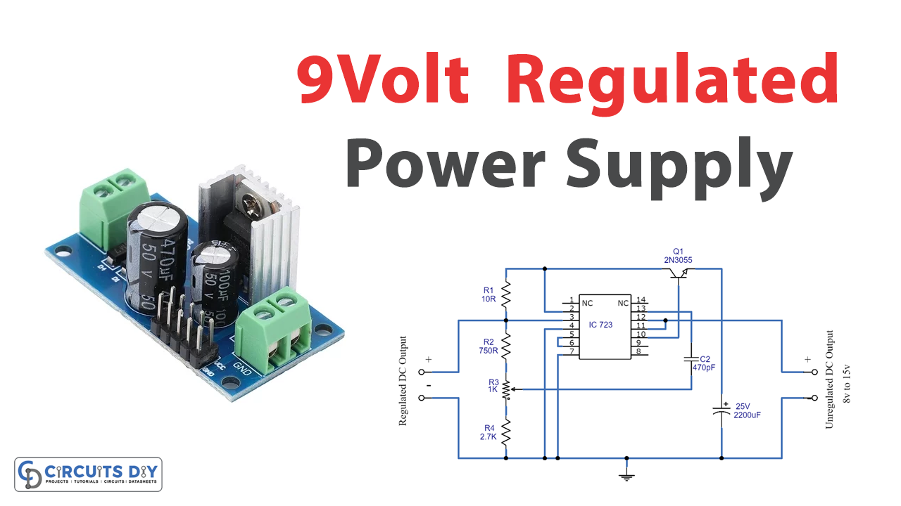
You should always make sure to use an appropriate current limit when powering sensitive components. A regulated power supply converts unregulated AC to a constant DC. It is used to ensure that the output remains constant even if the input changes. A regulated power supply will usually have a knob to select a current limit and a knob to select a voltage. When a load is placed across the outputs of the power supply, the supply will attempt to maintain the selected open circuit voltage across the load. The current will continue to rise to maintain the selected voltage until the selected current limit is reached. At this point, the voltage across the load will be equal to the selected current multiplied by the load impedance. Here we design a 9V regulated power supply by using the famous linear regulator IC 723.
Hardware Required
| S.No | Components | Value | Qty |
|---|---|---|---|
| 1 | IC | 723 | 1 |
| 2 | Transistor | 2N3055 | 1 |
| 3 | Capacitor | 2200uF/25V,470pF | 1,1 |
| 4 | Resistor | 2.7K,750Ω,10Ω | 1,1,1 |
| 5 | Variable Resistor | 1KΩ | 1 |
| 6 | Connecting Wires | – | – |
| 7 | Battery | 15V | 1 |
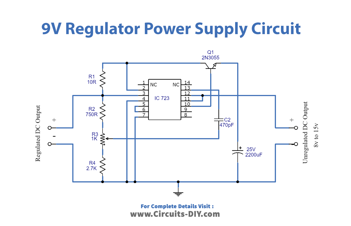
Circuit Diagram
Working Explanation
As we can see, this circuit is constructed with linear regulator IC 723 and a few other components like a resistor, capacitor, and transistor. Here we can get a different level of output DC by varying variable resistor R3, which is placed near regulated DC output terminals. As this circuit illustrated without step-down transformer and rectifier circuits, it is compulsory to convert the AC power supply into DC first. This circuit is designed to give a 9 V regulated power supply.
Applications
- Can be used as mobile phone chargers.
- Various oscillators & amplifiers.