Today we are going to demonstrate a very fun and interesting project of Arduino Solenoid Door Lock using RFID. There are many different ways of making door locks but here we are using RFID, aka Radio Frequency Identification. RFID is an inexpensive and accessible technology used in many applications like access control, asset tracking, people tracking, security, etc. In hotel rooms or offices, you must have seen the door locks are opened by placing a car near an RFID reader, and it opens.
We can also make a simple RFID door lock, but Solenoid Lock is used in this circuit. Solenoid Lock is a type of lock that works on an electronic-mechanical locking mechanism and has a slug. That slug moves inside and keeps the door locked when the DC power is applied and it will retain its position when the power is removed. The slug moves outside and locks the door when the power is disconnected. To drive a solenoid lock we need a power source that gives 12 volts at 500mA output current.
Hardware Requirements
| S.no | Component | Value | Qty |
|---|---|---|---|
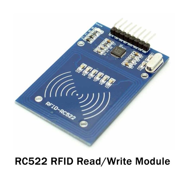
| 1 | RFID | RC522 | 1 |
| 2 | Arduino Uno | – | 1 |
| 3 | Solenoid Lock | – | 1 |
| 4 | Relay Module | 12V | 1 |
| 5 | Resistor | 100K | 1 |
| 6 | Hall Effect Sensor | – | 1 |
| 7 | Buzzer | – | 1 |
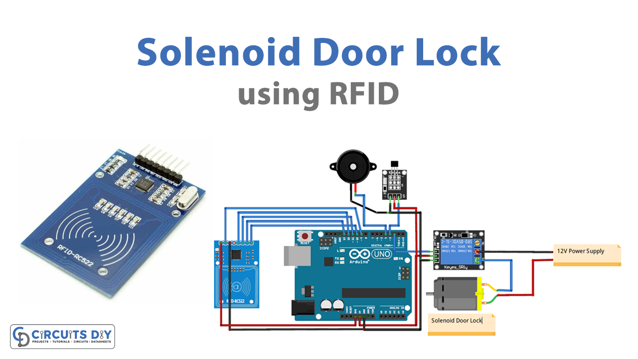
Circuit Diagram

Connections
This table shows the connections between Arduino and RFID. The digital pin 4 of Arduino has the positive pin of the buzzer connected to it, and both of their GND pins are connected with each other. A 10K resistor is connected between the VCC and OUT pin of the Hall effect sensor, and the solenoid lock is connected to Arduino through the relay module.
| RFID Pin | Arduino Uno Pin |
|---|---|
| SDA | Digital 10 |
| SCK | Digital 13 |
| MOSI | Digital 11 |
| MISO | Digital 12 |
| IRQ | Unconnected |
| GND | GND |
| RST | Digital 9 |
| 3.3V | 3.3V |
| Hall Effect Sensor Pin | Arduino Uno Pin |
| 5V | 5V |
| GND | GND |
| OUT | 3 |
Code
#include <SPI.h>
#include <MFRC522.h>
int hall_sensor = 3;
int state,lockread;
int Buzzer = 4;
const int LockPin = 2;
#define SS_PIN 10
#define RST_PIN 9
MFRC522 mfrc522(SS_PIN, RST_PIN);   // Create MFRC522 instance.
void setup()
{
  Serial.begin(9600);   // Initiate a serial communication
  pinMode(LockPin, OUTPUT);
  pinMode(Buzzer, OUTPUT);
  pinMode(hall_sensor, INPUT);
  SPI.begin();      // Initiate  SPI bus
  mfrc522.PCD_Init();   // Initiate MFRC522
  //Serial.println("Approximate your card to the reader...");
  // Serial.println();
  digitalWrite(LockPin, LOW);
}
void readsensor()
{
 lockread = digitalRead(LockPin);
 state = digitalRead(hall_sensor);
 //Serial.print(lockread);
 //Serial.print(state);
 // delay(2000);
}
void loop()
{
  readsensor();
  sensor();
  // Look for new cards
  if ( ! mfrc522.PICC_IsNewCardPresent())
  {
    return;
  }
  // Select one of the cards
  if ( ! mfrc522.PICC_ReadCardSerial())
  {
    return;
  }
  //Show UID on serial monitor
  String content= "";
  byte letter;
  for (byte i = 0; i < mfrc522.uid.size; i++)
  {
     content.concat(String(mfrc522.uid.uidByte[i] < 0x10 ? " 0" : " "));
     content.concat(String(mfrc522.uid.uidByte[i], HEX));
  }
  //Serial.println();
  //Serial.print("Message : ");
  content.toUpperCase();
 if (content.substring(1) == "60 4E 07 1E" ) //change here the UID of the card/cards that you want to give access
  {
    digitalWrite(LockPin, HIGH);
    Serial.print("Door Unlocked");
    digitalWrite(Buzzer, HIGH);
    delay(2000);
    digitalWrite(Buzzer, LOW);

    sensor();
    }
  else
{
Serial.println("You are not Authorised");
digitalWrite(Buzzer, HIGH);
delay(2000);
digitalWrite(Buzzer, LOW);
  }
}
void sensor()
{
readsensor();
if (lockread == HIGH){
readsensor();
if(state==LOW){
digitalWrite(LockPin, LOW);
Serial.print("Door Closed");
digitalWrite(Buzzer, HIGH);
delay(2000);
digitalWrite(Buzzer, LOW);
    }
}
}
Working Explanation
This circuit’s working is simple; we are using a Solenoid Door Lock and controlling it with RFID and Arduino. A Hall Effect sensor and a magnet are used for the detection purposes of door movement. The Hall Effect sensor is placed on the door frame, and the magnet is placed at the door itself; when they are close to each other, the hall effect sensor is in a low state, and the door will remain closed. When the door is moved it causes the Hall Effect sensor and magnet to break contact and the hall effect sensor will be in a high state, which means the door is open now. The locking and unlocking of the door is working on this Hall Effect mechanism.
Circuit Testing
When you are done with the coding and the circuit you will have to test the door lock. Mount the circuit on the door frame and the magnet on the door so that the door’s movement can be detected. Scan the authorized RFID card to open the door lock. It will open until the hall effect sensor output is high and when the door reaches near the sensor, its output will become low and the door will be locked again.