Introduction
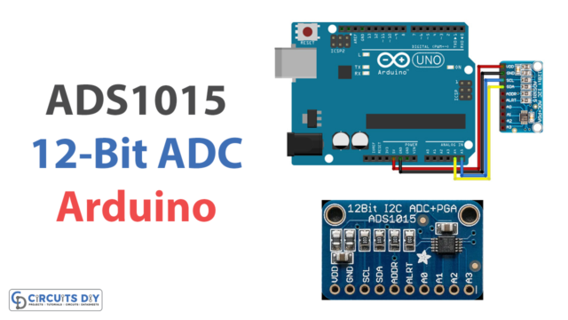
In this article, we are interfacing an ADS1118 16-bit ADC module with an Arduino. An analog-to-digital converter (ADC) is a device that converts an analog signal, such as the voltage output of a sensor, into a digital representation that a microcontroller can understand and process. An ADC can be used to read and process analog signals on the Arduino, which is a microcontroller.
There are several ADCs available for use with the Arduino, ranging from simple, low-resolution converters to high-precision, high-resolution devices. For this project, we are using ADS1118 16-Bit ADC.
There are just a few basic steps, and no additional hardware is needed for the interface. As a result, the code is simpler to comprehend. Let’s dive in right now and find out more!
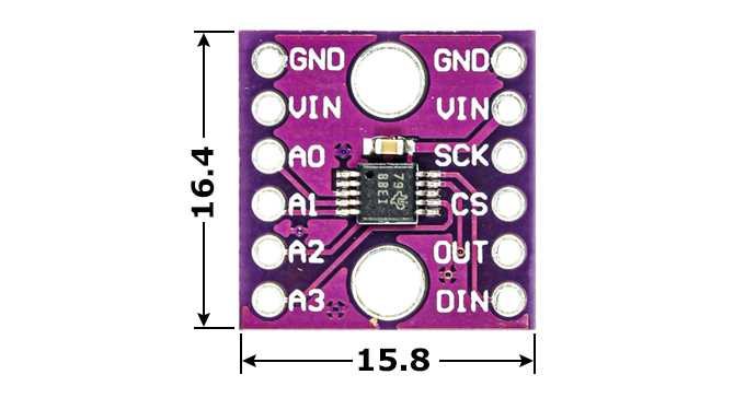
What is ADS1118 16-Bit ADC Module?
The ADS1118 is a precise, low-power, 16-bit analog-to-digital converter (ADC). The ADS1118 combines a PGA, voltage reference, oscillator, and temperature sensor. These capabilities, together with a broad power supply range from 2 V to 5.5 V, make the ADS1118 appropriate for power- and space-constrained sensor-measurement applications.
Hardware Components
You will require the following hardware for Interfacing ADS1118 16-Bit ADC Module with Arduino.
| S.no | Component | Value | Qty |
|---|---|---|---|
| 1. | Arduino UNO | – | 1 |
| 2. | Converter Module | ADS1118 | 1 |
| 3. | Ceramic Capacitor | 100NF | 1 |
| 4. | Resistor 1/4W | 10KΩ | 1 |
| 5. | Breadboard | – | 1 |
| 6. | Jumper Wires | – | 1 |
Steps Interfacing ADS1118 16-Bit ADC Module with Arduino
Get all the required components that are listed above in the hardware section. Once you have them all, follow the given steps:
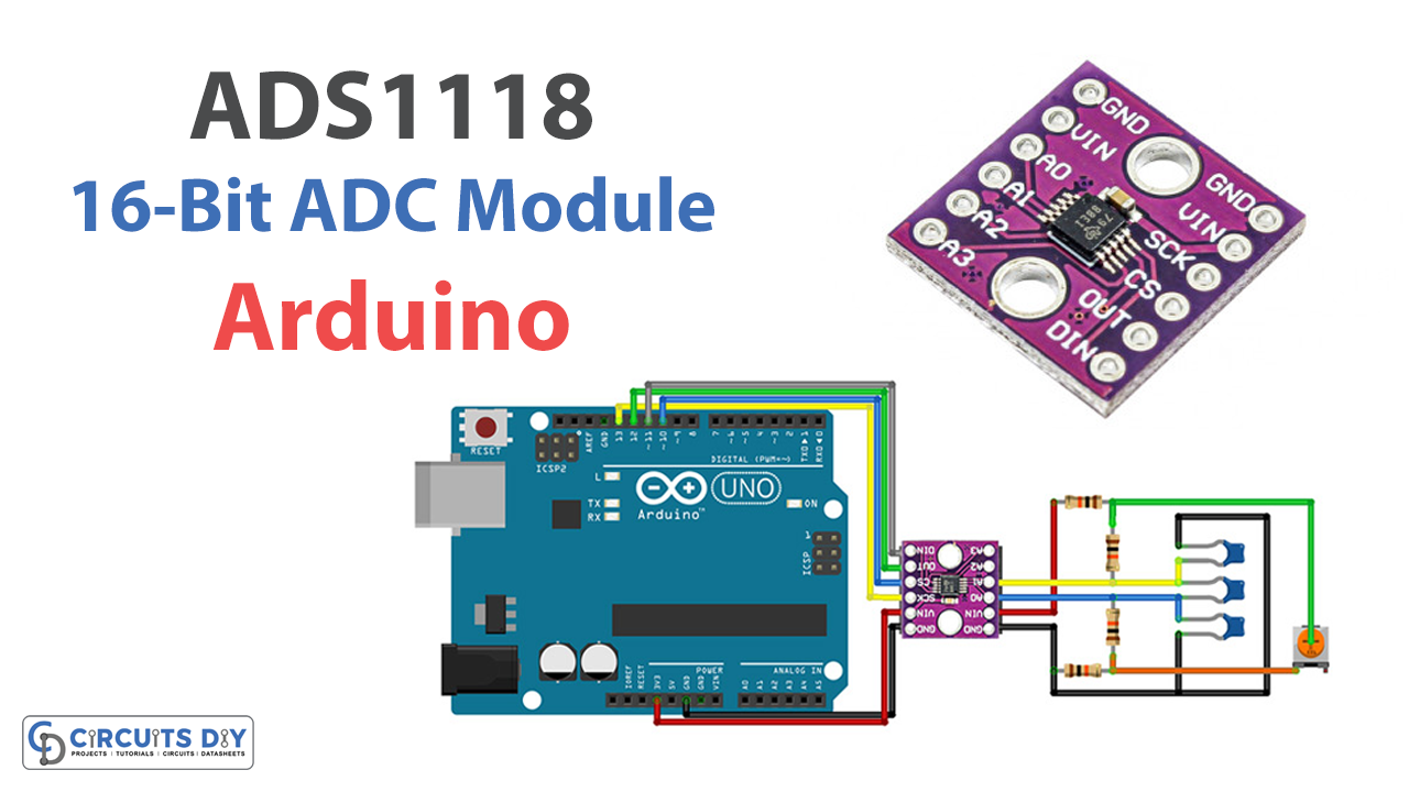
Schematic
Make connections according to the circuit diagram given below.

Installing Arduino IDE
First, you need to install Arduino IDE Software from its official website Arduino. Here is a simple step-by-step guide on “How to install Arduino IDE“.
Installing Libraries
Before you start uploading a code, download and unzip the following libraries at /Progam Files(x86)/Arduino/Libraries (default), in order to use the sensor with the Arduino board. Here is a simple step-by-step guide on “How to Add Libraries in Arduino IDE“.
Code
Now copy the following code and upload it to Arduino IDE Software.
#include "ADS1118.h"
#include <SPI.h>

Definition of the Arduino pin to be used as the chip select pin (SPI CS pin) Example: pin 5
#define CS 10

//Creating an ADS1118 object (object's name is ads1118)
ADS1118 ads1118(CS);


void setup(){
    Serial.begin(115200);
    ads1118.begin(); //Initialize the ADS1118. Default setting: PULLUP RESISTOR, ADC MODE, RATE 8SPS, SINGLE SHOT, ±0.256V, DIFFERENTIAL AIN0-AIN1

    /*
     *  EXAMPLES:
*  The lines above in this method are needed only if you want to change the default setting. Use them to fit your needs
     *  If you need to take care of noise and the ENOB (Effective Number of Bits) see the tables at the end of this file
     */

Changing the sampling rate
       Available values: RATE_8SPS, RATE_16SPS, RATE_32SPS, RATE_64SPS, RATE_128SPS, RATE_250SPS, RATE_475SPS, RATE_860SPS */
    ads1118.setSamplingRate(ads1118.RATE_16SPS);             //Using the setter method to change the sampling rate
    //ads1118.configRegister.bits.rate=ads1118.RATE_8SPS;   // // driving the configuration register directly. Uncomment if you want to use this way

    /* Changing the input selected.
       Available values: Diferential inputs: DIFF_0_1, DIFF_0_3, DIFF_1_3, DIFF_2_3.
                         Single ended input: AIN_0, AIN_1, AIN_2, AIN_3*/
    ads1118.setInputSelected(ads1118.DIFF_0_1);             //Using the setter method to change the input selected
    //ads1118.configRegister.bits.mux=ads1118.DIFF_0_1;     // // driving the configuration register directly. Uncomment if you want to use this way

    /* Changing the full scale range.
       Available values: FSR_6144 (±6.144V)*, FSR_4096(±4.096V)*, FSR_2048(±2.048V), FSR_1024(±1.024V), FSR_0512(±0.512V), FSR_0256(±0.256V).
       (*) No more than VDD + 0.3 V must be applied to this device. */
    ads1118.setFullScaleRange(ads1118.FSR_0256);            //Using the setter method to change the full scale range
    //ads1118.configRegister.bits.pga=ads1118.FSR_0256;     // // driving the configuration register directly. Uncomment if you want to use this way


    /* Setting to continuous conversion mode */
    ads1118.setContinuousMode();                            //Using the setter method to set it to continuous mode
    //ads1118.configRegister.bits.operatingMode=CONTINUOUS; // // driving the configuration register directly. Uncomment if you want to use this way

    /* Setting to single shot conversion mode */
    ads1118.setSingleShotMode();                            //Using the setter method to set it to "single shot conversion and power down" mode
    //ads1118.configRegister.bits.operatingMode=SINGLE_SHOT;//driving the configuration register directly. Uncomment if you want to use this way

    /* Disabling the pull-up resistor */
    ads1118.disablePullup();                                //Using the setter method to disable the pull-up resistor in Dout
    //ads1118.configRegister.bits.pullUp=PULLUP;            // // driving the configuration register directly. Uncomment if you want to use this way

    /* Enabling the pull-up resistor */
    ads1118.enablePullup();                                 //Using the setter method to enable the pull-up resistor in Dout
    //ads1118.configRegister.bits.pullUp=NO_PULLUP;         // // driving the configuration register directly. Uncomment if you want to use this way
}


void loop(){
//    Serial.println(String(ads1118.getTemperature(),6)+" C"); //Getting temperature
    Serial.println(String(ads1118.getMilliVolts(),10)+"mV"); // // Getting millivolts measured in the input selected

    //Serial.println(String(ads1118.getMilliVolts(ads1118.DIFF_0_1),10)+"mV"); //Specifying the input to be selected

    delay(200); //You can use a delay to save power. The ADS1118 will be in a power-down state during all the delay time. Optional

}

/*
              Table 1. Noise in μVRMS (μVPP) at VDD = 3.3 V   [1]
                DATA RATE FSR (Full-Scale Range)
  (SPS) ±6.144 V        ±4.096 V     ±2.048 V       ±1.024 V        ±0.512 V        ±0.256 V
  8     187.5 (187.5)   125 (125)    62.5 (62.5)    31.25 (31.25)   15.62 (15.62)   7.81 (7.81)
  16    187.5 (187.5)   125 (125)    62.5 (62.5)    31.25 (31.25)   15.62 (15.62)   7.81 (7.81)
  32    187.5 (187.5)   125 (125)    62.5 (62.5)    31.25 (31.25)   15.62 (15.62)   7.81 (7.81)
  64    187.5 (187.5)   125 (125)    62.5 (62.5)    31.25 (31.25)   15.62 (15.62)   7.81 (7.81)
  128   187.5 (187.5)   125 (125)    62.5 (62.5)    31.25 (31.25)   15.62 (15.62)   7.81 (12.35)
  250   187.5 (252.09)  125 (148.28) 62.5 (84.03)   31.25 (39.54)   15.62 (16.06)   7.81 (18.53)
  475   187.5 (266.92)  125 (227.38) 62.5 (79.08)   31.25 (56.84)   15.62 (32.13)   7.81 (25.95)
  860   187.5 (430.06)  125 (266.93) 62.5 (118.63)  31.25 (64.26)   15.62 (40.78)   7.81 (35.83)


      Table 2. ENOB from RMS Noise (Noise-Free Bits from Peak-to-Peak Noise) at VDD = 3.3 V
                DATA RATE FSR (Full-Scale Range)
  (SPS)   ±6.144 V    ±4.096 V   ±2.048 V     ±1.024 V    ±0.512 V    ±0.256 V
  8       16 (16)     16 (16)    16 (16)      16 (16)     16 (16)     16 (16)
  16      16 (16)     16 (16)    16 (16)      16 (16)     16 (16)     16 (16)
  32      16 (16)     16 (16)    16 (16)      16 (16)     16 (16)     16 (16)
  64      16 (16)     16 (16)    16 (16)      16 (16)     16 (16)     16 (16)
  128     16 (16)     16 (16)    16 (16)      16 (16)     16 (16)     16 (15.33)
  250     16 (15.57)  16 (15.75) 16 (15.57)   16 (15.66)  16 (15.96)  16 (14.75)
  475     16 (15.49)  16 (15.13) 16 (15.66)   16 (15.13)  16 (14.95)  16 (14.26)
  860     16 (14.8)   16 (14.9)  16 (15.07)   16 (14.95)  16 (14.61)  16 (13.8)


  [1] Texas Instruments, "ADS1118 Ultrasmall, Low-Power, SPIâ„¢-Compatible, 16-Bit Analog-to-Digital
Converter with Internal Reference and Temperature Sensor,"  ADS1118 datasheet, SBAS457E [October 2010—October 2015].

  Note: This information is taken from http://www.ti.com
        Copyright © 2010–2015, Texas Instruments Incorporated
*/
Let’s Test It
Once you are done with the circuit wiring and the uploading of code, it is now time to test the circuit. Open the serial monitor to observe the readings.
Working Explanation
Let’s look into the program to understand the coding:
- The code is set up first by using an ADS1118 analog-to-digital converter (ADC) library.
- In the void setup() function, the ADC is first initialized by calling the begin() function of the ADS1118 object. Then, various settings of the ADC are modified using the setter functions provided by the ADS1118 class. These setter functions allow you to set the sampling rate, input selection, full-scale range, operating mode, and the pull-up resistor on the Dout pin.
- In the void loop() function, the ADC measures the temperature and the voltage on the selected input. The getTemperature() method returns the temperature in Celsius, while the getMilliVolts() function returns the voltage in millivolts. We also specify the input to be measured by passing the input selection as an argument to the getMilliVolts() function.
- Finally, the code has a delay of 200 milliseconds between each measurement.
Applications
- Automation and process control
- Temperature measurement, etc
Conclusion.
We hope you have found this Interfacing ADS1118 16-Bit ADC Circuit very useful. If you feel any difficulty in making it feel free to ask anything in the comment section.