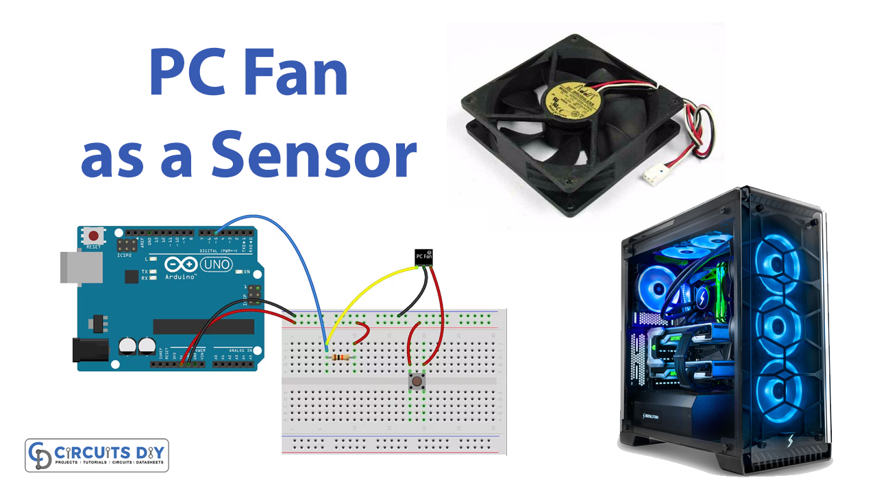
Introduction
In this tutorial, let’s make utilization of the PC fan. Everyone has used a computer, and you may have seen an active cooling fan on your computer. These Fans are used to circulate air across a heat sink to cool a specific component to move heated air out of the case and pull cooler air in from the outside. However, that is not what we are going to discuss today. Instead, we will use that PC fan as a sensor.
Different fundamental arrangements exist for PC fans. We’ll employ a three-wire sensor. The three-wire fan is perfect for use as a sensor. A pulse can be seen between the ground and the third wire while the fan rotates. The pulse is produced by a built-in hall-effect sensor that monitors the rotation of the motor’s magnets.
Hardware Components
You will require the following hardware for using a PC Fan Sensor.
Steps Making PC Fan as a Sensor
To use a PC Fan as a Sensor you need an Arduino and some wires along with a PC fan. Once you have them; follow the given steps:
Schematic
Make connections according to the circuit diagram given below.
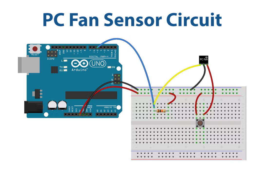
Wiring / Connections
| Arduino | 3-Wire PC Fan | Resistor |
|---|---|---|
| 5V | RED through Button | One Pin |
| GND | Black | |
| D5 | Yellow | Other Pin |
Installing Arduino IDE
First, you need to install Arduino IDE Software from its official website Arduino. Here is a simple step-by-step guide on “How to install Arduino IDE“.
Installing Libraries
Before you start uploading a code, download and unzip the following libraries at /Progam Files(x86)/Arduino/Libraries (default), in order to use the sensor with the Arduino board. Here is a simple step-by-step guide on “How to Add Libraries in Arduino IDE“.
Code
Now copy the following code and upload it to Arduino IDE Software.
#include <Arduino.h>
#include "FanMonitor.h"

// ***
// *** Pins
// ***
#define FAN_MONITOR_PIN 5

// ***
// *** Define the FanMonitor instance to monitor
// *** the 3-wire fan.
// ***
FanMonitor _fanMonitor = FanMonitor(FAN_MONITOR_PIN, FAN_TYPE_BIPOLE);

void setup()
{
  // ***
  // *** Initialize the serial port.
  // ***
  Serial.begin(115200);

  // ***
  // *** Initialize the fan monitor.
  // ***
  _fanMonitor.begin();
}

void loop()
{
  // ***
  // *** Get the fan speed.
  // ***
  uint16_t rpm = _fanMonitor.getSpeed();
  // ***
  // *** Print the speed to the serial port.
  // ***
  Serial.print("Speed = "); Serial.print(rpm); Serial.println(" RPM");
  // ***
  // *** Delay 1 second.
  // ***
  delay(1000);
}
Let’s Test It
It’s time to test the circuit at this stage. Open the serial monitor after uploading the code to the Arduino. Readings start to appear. The serial monitor will display the speed in RPMs.
Working Explanation
You need to understand the coding in order to understand the working:
- First, we include libraries to communicate with Arduino and PC fans.
- Then Create a FanMonitor object instance to use it further.
- Initialize the instance in the void setup.
- Finally, whenever you wish to determine the fan’s speed, call getSpeed(). By calling the function Serial.begin, you may print that speed in rpm on a serial monitor
- Give a little delay to get the next reading
A hall-effect sensor, which is a built-in sensor, generates the pulse by monitoring the rotation of the motor’s magnets. These pulses would be read by Arduino would be shown on the Serial monitor
Applications
- This can be used to measure the airflow.
Conclusion.
We hope you have found this PC Fan as a Sensor very useful. If you feel any difficulty in making it feel free to ask anything in the comment section.


Please,can you send me step by step approach to Arduino programme