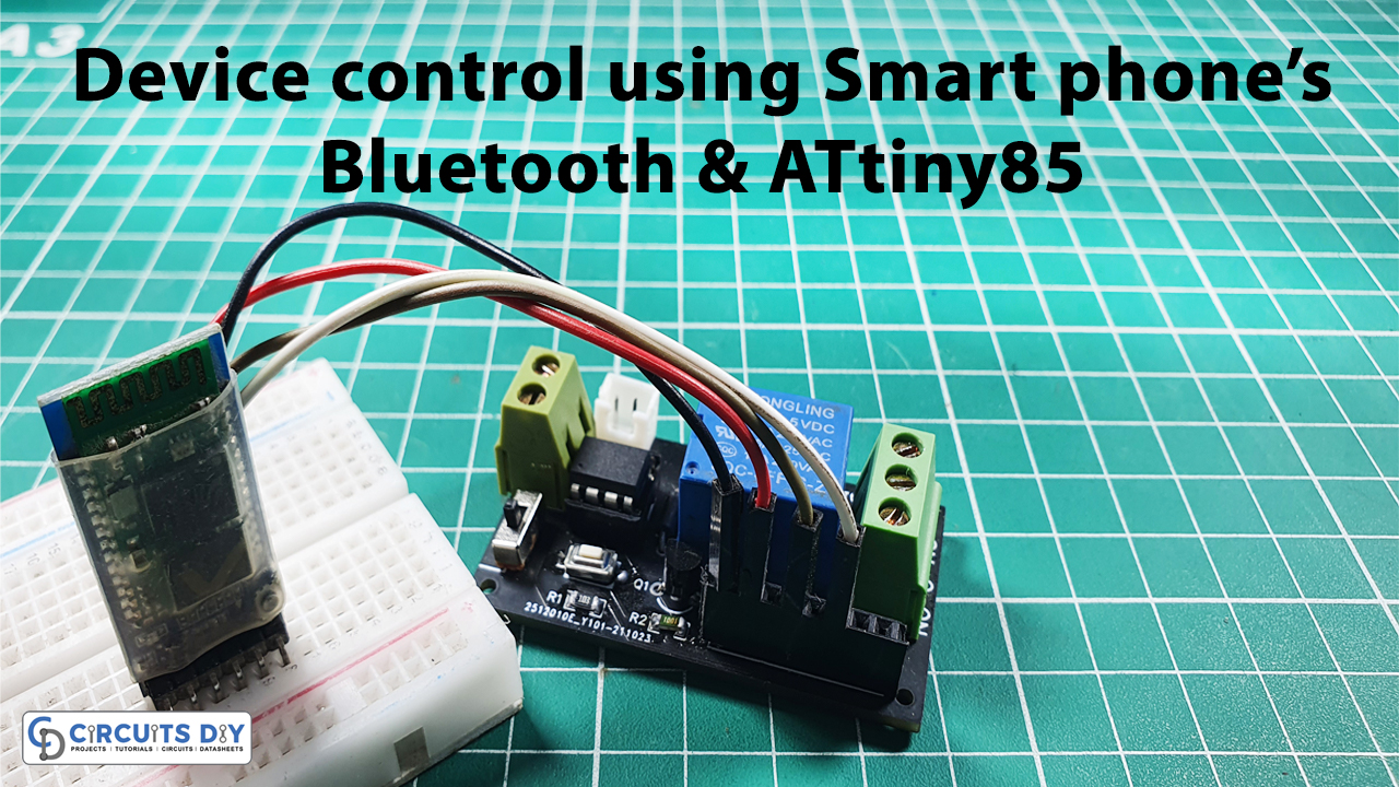
Introduction
We are living in the smart era, where we, humans want everything at our fingertips. Sometimes we don’t want to waste our time on small matters like turning ON/OFF the device switches. And, for this reason, the concept of smart home automation is rising, where a human only needs his/her phone to switch ON/OFF his home, or office devices. Thus, making this wasn’t a cup of tea. Your devices must have a Bluetooth module on them. The circuit also requires coding behind it. So, are you ready to make that circuit with us? Because in this tutorial, we are going to make a device control using smart phone’s Bluetooth and Attiny85. Along with Attiny85, the circuit is also using the HC-05 Bluetooth module to turn ON/OFF the relay. So, before making the circuit, let us briefly discuss this Bluetooth module.
Overview of Bluetooth Module
The HC-05 is a common wireless full-duplex module that may be used in a variety of projects. You may use this module to communicate between two microcontrollers, with any Bluetooth-enabled device, such as a cellphone. The HC-05 has two working modes: data and AT command. The data model allows you to transmit and receive data from other Bluetooth devices, while the AT command mode allows you to adjust the default device settings.
Interfacing with Microcontroller
Because the HC-05 module uses the Serial Port Protocol, it is quite simple to interface it to microcontrollers. Simply connect the Rx (receiver) pin of the Bluetooth module to the Tx (transmitter) of the microcontroller and the Tx pin of the module to the Rx of the microcontroller with a 5V supply.
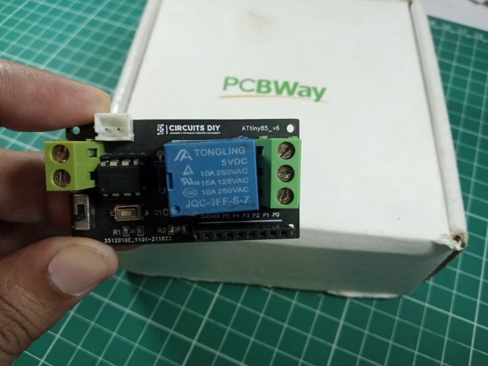
PCBWay commits to meeting the needs of its customers from different industries in terms of quality, delivery, cost-effectiveness, and any other demanding requests. As one of the most experienced PCB manufacturers in China. They pride themselves to be your best business partners as well as good friends in every aspect of your PCB needs.
Hardware Components
The following components are required to make Device Control Circuit
| S.no | Component | Value | Qty |
|---|---|---|---|
| 1. | PCB | – | 1 |
| 2. | Attiny85 | – | 1 |
| 3. | Bluetooth module | HC-05 | 1 |
| 4. | Relay module | 5V | 1 |
| 5. | Resistor | 1K, 10K | 1, 1 |
| 6. | Push Button | – | 1 |
| 7. | Transistor | BC547 | 1 |
| 8. | Diode | 1N4007 | 1 |
| 9. | Headers | (3, 8) Pins | 1, 1 |
ATTiny85 Pinout
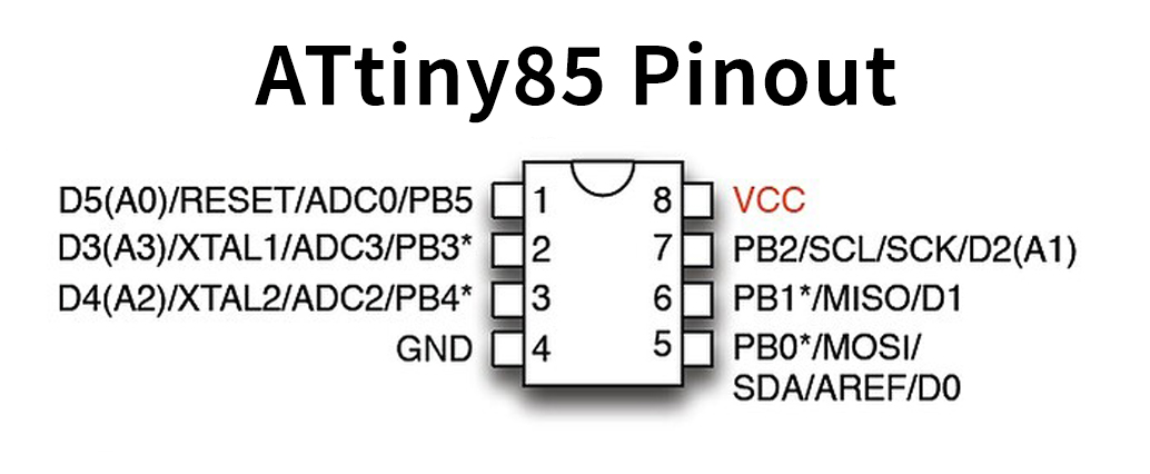
For a detailed description of pinout, dimension features, and specifications download the datasheet of ATTiny85
BC547 Pinout

For a detailed description of pinout, dimension features, and specifications download the datasheet of BC547
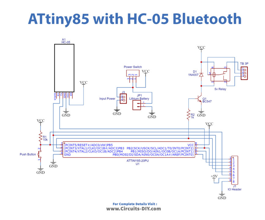
Device Control Circuit
Arduino Code
#include<SoftwareSerial.h>
#define relay_pin 3
SoftwareSerial BT_serial(2,4);// TX,RX of HC-05
char ch;
void setup()
{
  pinMode(4,OUTPUT);
  pinMode(2,INPUT);
  pinMode(3,OUTPUT);
  BT_serial.begin(9600);
  delay(2000);
  BT_serial.println("Bluetooth connected");
  delay(1000);
  BT_serial.println("send 1/0 to turn ON/OFF device");
}
void loop()
{
  while(BT_serial.available())
    {
       if(BT_serial.available()>0)
        {
          ch = BT_serial.read();
          if(ch == '1')
{
  digitalWrite(relay_pin,HIGH);
  BT_serial.print("Device is ON");
}
          if(ch == '0')
   {
  digitalWrite(relay_pin,LOW);
  BT_serial.print("Device is OFF");
}
        }
    }
}
Working Explanation
For this Device control using smart phone’s Bluetooth and ATtiny85, connect the components according to the circuit diagram given above, and upload the code in the Attiny85 microcontroller. Now when a 5V supply applies to the circuit, the HC05 module will begin flashing to signify that it is looking for a Bluetooth device to pair with. Open the application for Bluetooth control on your phone, there are a variety of such apps in the Google Play Store. You can find it there. The application will search and pair with the HC-05 Bluetooth module.
Now send commands through that app to turn ON/OFF the relay. Send the instruction ‘1’ from the smartphone to switch on the relay. Send the command ‘0’ from the smartphone to switch off the relay.
Code Explanation
- Firstly, we have included the relevant libraries for the code.
- In void setup, define input, and output pins.
- In the void loop, The code notifies the person’s smartphone that the HC05 module is connected via Bluetooth and transmits instruction 1/0 to switch the device on or off. The code then waits for any data coming from the serial port. If the instruction ‘1’ or ‘0’ is received, the relay will be switched on/off by sending HIGH/LOW to the relay module input pin. It also sends a notification to the user’s smartphone when the relay is turned on or off.
Application and Uses
- We can utilize the circuit in-home, and office automation system to turn ON/OFF the appliances.
- Smart automation devices.