Overview
In today’s age of electronics, it is important to have a thorough understanding of design components and schemes that have a significant impact on the process flow of any project. When it comes to directional and speed control of motors, having a thorough understanding of servo motors is imperative. Combining this knowledge with the processing power of an ESP32 can open a world of opportunities for any designer or hobbyist looking to step into the domain of automation and control.
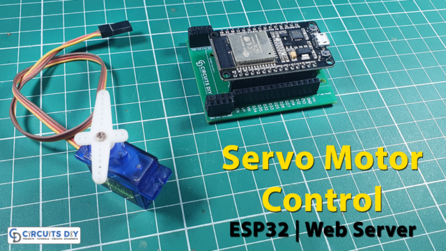
In today’s tutorial, we are going to learn how to control an SG90 servo motor using an ESP32-WROOM microcontroller.
Introduction to Servo Motor
A servo motor is a type of motor commonly used in various applications to control the position, speed, and movement of mechanical components. Servo motors are an integral component in a wide variety of electrical/electronic systems and design implementations such as control systems, process automation, emergency response electronics, etc.
If you want to learn more about Servo Motor, read this article on Servo Motors.
Hardware Components
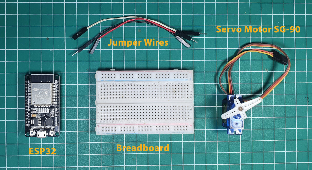
You’ll need the following hardware components to get started:
| Components | Value / Model | Qty |
|---|---|---|
| ESP32 | – | 1 |
| Servo Motor | SG-90 | 1 |
| Breadboard | – | 1 |
| Jumper Wires | – | 1 |
| DC Power for ESP32 | 5V | 1 |
Steps-by-Step Guide
(1) Setting up Arduino IDE
Download Arduino IDE Software from its official site. Here is a step-by-step guide on “How to install Arduino IDE“.
(2) ESP32 in Arduino IDE
There’s an add-on that allows you to program the ESP32 using the Arduino IDE. Here is a step-by-step guide on “How to Install ESP32 on Arduino IDE“.
(3) Include Libraries
Before you start uploading a code, download and unzip the Servo.h library at /Program Files(x86)/Arduino/Libraries (default). Here is a step-by-step guide on “How to Add Libraries in Arduino IDE“.
(4) Schematic
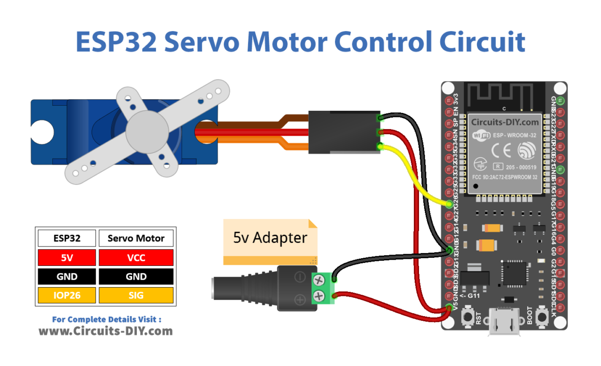
Make connections according to the circuit diagram given below.
Wiring / Connections
| ESP32 | Servo Motor |
|---|---|
| 5V | VCC |
| GND | GND |
| GIOP26 | SIG |
(5) Uploading Code
Now copy the following code and upload it to Arduino IDE Software.
/* Circuits DIY
 * For Complete Details Visit
 * https://www.circuits-diy.com/esp32-tutorial-servo-motor-control
 */

#include <Servo.h>
#define SERVO_PIN 26 // ESP32 pin GPIO26 connected to servo motor
Servo servoMotor;

void setup() {
  servoMotor.attach(SERVO_PIN);  // attaches the servo on ESP32 pin
}

void loop() {

  // rotates from 0 degrees to 180 degrees
  for (int pos = 0; pos <= 180; pos += 1) {
    // in steps of 1 degree
    servoMotor.write(pos);
    delay(15); // waits 15ms to reach the position
  }

  // rotates from 180 degrees to 0 degrees
  for (int pos = 180; pos >= 0; pos -= 1) {
    servoMotor.write(pos);
    delay(15); // waits 15ms to reach the position
  }
}
How code works
#include <Servo.h>This line includes the Arduino Servo library, which provides functions to control servo motors.
#define SERVO_PIN 26 // ESP32 pin GPIO26 connected to servo motorThis line defines a symbolic constant SERVO_PIN with a value of 26. This constant is used to specify the pin to which the servo motor is connected.
Servo servoMotor;This line declares an instance of the Servo class called servoMotor, which will be used to control the servo motor.
void setup() {
  servoMotor.attach(SERVO_PIN);  // attaches the servo on ESP32 pin
}
In the setup() function, the attach() method is called on the servoMotor object, which attaches the servo motor to the specified pin (GPIO 26 in this case).
void loop() {
  // rotates from 0 degrees to 180 degrees
  for (int pos = 0; pos <= 180; pos += 1) {
    // in steps of 1 degree
    servoMotor.write(pos);
    delay(15); // waits 15ms to reach the position
  }

  // rotates from 180 degrees to 0 degrees
  for (int pos = 180; pos >= 0; pos -= 1) {
    servoMotor.write(pos);
    delay(15); // waits 15ms to reach the position
  }
}
In the loop() function, there are two for loops. The first loop gradually increases the servo motor’s position from 0 degrees to 180 degrees in 1-degree increments. The servoMotor.write(pos) call sets the servo motor’s angle to the value of pos. The delay(15) call adds a 15-millisecond delay to allow the servo motor to reach the desired position smoothly. The second loop then decreases the servo motor’s position from 180 degrees back to 0 degrees in the same manner.
This code effectively makes the servo motor oscillate between 0 and 180 degrees continuously with a 15-millisecond delay at each position change.
Working Explanation
The work of this project is as follows. When connected to an ESP32 WROOM microcontroller, the servo motor’s position is made controllable through a series of pulse-width modulation (PWM) signals directed by the code control statements mentioned above. By modulating the duty cycle of the PWM signals generated by the ESP32, the motor is directed to rotate within a specified angle range, typically 0 to 180 degrees.
Applications
- Robotics
- Automation
- Aerospace
- CNC
Conclusion
Controlling a servo motor with an ESP32 opens up a world of possibilities for creating projects that require precise motion control. This tutorial covered the basic setup and code required to control a servo motor using an ESP32 development board