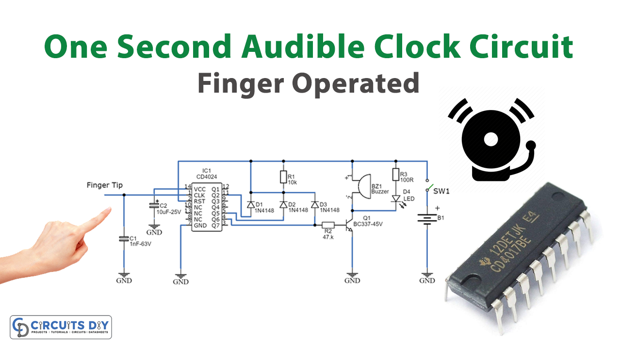
Overview
In today’s tutorial, we are going to make an “Finger Operated One Second Audible Clock Circuit” using a CD4024 IC.
This precise one-pulse-per-second clock is constructed using a few standard components and synchronized with a 50 or 60 Hertz mains power source, albeit without a direct physical link to it. A sound beep akin to a metronome click and/or a visible flash marks each one-second interval, making it advantageous for various applications requiring precise time-delay counting in seconds. The circuit is established around a CMOS 4024 counter/divider chip and three diodes, strategically configured to divide the frequency of the incoming signal at pin #1 by 50 (or 60, refer to Notes).
The input impedance at pin #1 is exceptionally high, allowing a simple touch to the pin or a short conductor connected to it to generate the required input signal. Alternatively, wrapping a wire several times around any accessible mains cable or transformer can also serve as an input signal source. No additional connections are needed beyond this setup.
Hardware Components
To make this, you’ll need the following hardware components to get started:
| S.no | Components | Value | Qty |
|---|---|---|---|
| 1 | Integrated Circuit IC | IC1 = 4024-7 stage ripple counter IC | 1 |
| 2 | Transistors | Q1 = BC337-45V 800mA NPN Transistor | 1 |
| 3 | Diodes | D1 = 1N4148 D2 = 1N4148 D3 = 1N4148 D4 = LED-(Optional, any shape and color, see Notes) D5 = 1N4148-75V 150mA Diode | 1 1 1 1 1 |
| 4 | Polar Capacitors | C1 = 1nF-63V C2 = 10µF-25V C3 = 100nF-63V | 1 1 1 |
| 5 | Battery | B1 = 3 to 12V | 1 |
| 6 | Resistors | R1 = 10K R2 = 47.K R3 = 100R | 1 1 1 |
| 7 | Buzzer | BZ1 = Piezo sounder (incorporating 3KHz oscillator) | 1 |
| 8 | Switch | SW1 = SPST Toggle or Slide | 1 |
| 9 | Speaker | SPKR = 8 Ohm, 40 – 50mm diameter Loudspeaker | 1 |
Schematic
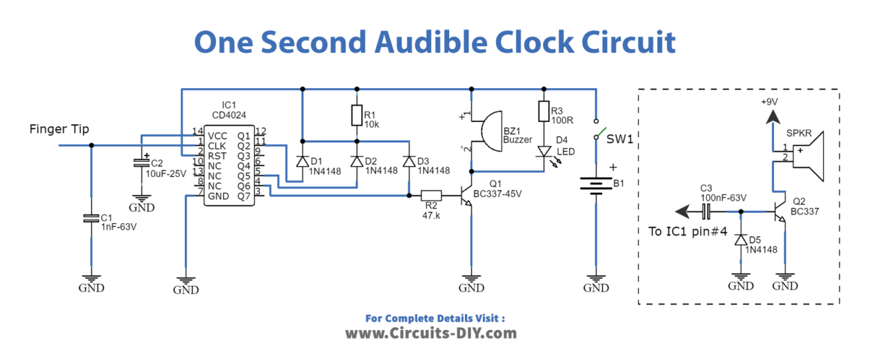
Important:
- To allow precise circuit operation in places where the mains supply frequency is rated at 60Hz, the circuit must be modified as follows: disconnect the Cathode of D1 from pin #11 of IC1 and connect it to pin #9. Add a further 1N4148 diode, connecting its Anode to R1 and the Cathode to pin #6 of IC1: that’s all!
- The circuit will work fine with battery voltages in the 3 -12V range.
- The visual display, formed by D4 and R3 is optional. Please note that the R3 value shown in the Parts list is suited to low battery voltages. If 9V or higher voltages are used, change its value to 1K.
- If a metronome-like click is needed, R2 and BZ1 must be omitted and substituted by the circuit shown enclosed in dashed lines, on the right of the diagram.
- The standby current drawing is negligible, so SW1 can be omitted.