Introduction
In today’s world, security is a major concern for homeowners, and many people are looking for effective ways to protect their homes from burglars and intruders. One of the most popular and reliable ways to secure your home is by using a GSM-based home security system. This system uses an IR sensor and a GSM SIM 900 module with an Arduino UNO microcontroller to detect any intrusion and alert the homeowner via text message or phone call.
The system is easy to install, cost-effective, and provides a reliable way to ensure the safety of your home and loved ones. In this article, we will dive deeper into how a GSM-based home security system using an IR Sensor and GSM SIM 900 module with an Arduino UNO microcontroller works and the benefits of using this type of system to secure your home.
Hardware Components
You will require the following hardware for the Home Security System.
| Components | Value | Qty |
|---|---|---|
| Arduino UNO | – | 1 |
| IR Sensor | – | 1 |
| GSM Module | SIM-900 | 1 |
| LED | – | 1 |
| Resistor | 220Ω | 1 |
| Breadboard | – | 1 |
| Jumper Wires | – | 1 |
Steps in Making a Home Security System
- Define the required libraries and create a SoftwareSerial object for the SIM900A module
#include <SoftwareSerial.h>
SoftwareSerial SIM900A(10,11);  // SoftSerial( RX , TX );
// 10 pin connect to TX of GSM SIM 900 Module
// 11 pin connect to RX of GSM SIM 900 Module- Define the variables and initialize the Serial and SIM900A connections in the setup() function
int val = 0 ;
void setup()
{
    Serial.begin(9600);   // sensor buart rate
    SIM900A.begin(9600);  // GSM buart rate
    pinMode(4,HIGH);      // LED connect D4
}- Read the IR sensor output value and print it to the Serial monitor in the loop() function
void loop()
{
  val = digitalRead(7);  //  IR sensor output pin connected D7
  Serial.println(val);   // see the value in serial monitor in Arduino IDE
  delay(1000);
  // Rest of the code goes here
}- Send data from the Serial monitor to the SIM900A module
if (Serial.available() > 0)
{
    // read the incoming byte from the serial monitor
    switch(Serial.read())
    {
        // send the byte to the SIM900A module
        case '0': SIM900A.write('0');
                  break;
        case '1': SIM900A.write('1');
                  break;
        // add more cases as needed for other characters
    }
}- Send an SMS message when an obstacle is detected
if (val == 0) // Check your sensor Value 1 or 0
{
Serial.println("Obstacle Detecting");
digitalWrite(4,HIGH); // LED ON
Serial.println("Sending Message");
SIM900A.println("AT+CMGF=1"); //Sets the GSM Module in Text Mode
delay(1000);
SIM900A.println("AT+CMGS=\"xxxxxxxxxx\"\r"); //Mobile phone number to send message, replace x by your number
delay(1000);
SIM900A.println("Some one IS comming, be safe");// Messsage content
delay(100);
SIM900A.println((char)26);// ASCII code of CTRL+Z
delay(1000);
Serial.println("Message has been sent ");
digitalWrite(4,LOW); // LED OFF
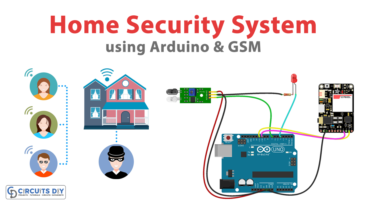
}Schematic
Make connections according to the circuit diagram given below.

Wiring / Connections
| Arduino | IR Sensor | SIM-900 Module | LED |
|---|---|---|---|
| 5V | 5V | ||
| GND | GND | GND | Negative – |
| D10 | TX | ||
| D11 | RX | ||
| D7 | OUT | ||
| D4 | Positive + |
Installing Arduino IDE
First, you need to install Arduino IDE Software from its official website Arduino. Here is a simple step-by-step guide on “How to install Arduino IDE“.
Installing Libraries
Before you start uploading a code, download and unzip the following libraries at /Program Files(x86)/Arduino/Libraries (default), in order to use the sensor with the Arduino board. Here is a simple step-by-step guide on “How to Add Libraries in Arduino IDE“.
Code
Now copy the following code and upload it to Arduino IDE Software.
 #include <SoftwareSerial.h>

  SoftwareSerial SIM900A(10,11);  // SoftSerial( RX , TX );
 // 10 pin connect to TX of GSM SIM 900 Module
 // 11 pin connect to RX of GSM SIM 900 Module
int val = 0 ;
void setup()
{
    Serial.begin(9600);   // sensor buart rate
    SIM900A.begin(9600);  // GSM buart rate
    pinMode(4,HIGH);      // LED connect D4
}
void loop()
{
  val = digitalRead(7);  //  IR sensor output pin connected D7
  Serial.println(val);   // see the value in serial mpnitor in Arduino IDE
  delay(1000);
  if (Serial.available()>0)
   switch(Serial.read())
    if (SIM900A.available()>0)
   Serial.write(SIM900A.read());
  if(val == 0 )  // Check your sensor Value 1 or 0
  // in my case IR sensor detect then value is 0 otherwise 1 you can change value
  {
     Serial.println ("Obstacle Detecting");
     digitalWrite(4,HIGH);   // LED ON
    Serial.println ("Sending Message");
  SIM900A.println("AT+CMGF=1");    //Sets the GSM Module in Text Mode
  delay(1000);
  Serial.println ("Set SMS Number");
   SIM900A.println("AT+CMGS=\"xxxxxxxxxx\"\r"); //Mobile phone number to send message, replace x by your number
  delay(1000);
  Serial.println ("Set SMS Content");
  SIM900A.println("Some one IS comming, be safe");// Messsage content
  delay(100);
  Serial.println ("Finish");
  SIM900A.println((char)26);// ASCII code of CTRL+Z

  delay(1000);
  Serial.println ("Message has been sent ");
  digitalWrite(4,LOW);   // LED OFF
  }
  }
Working Explanation
The code uses the SoftwareSerial library to create a new serial communication port on pins 10 and 11 of the Arduino board to communicate with the GSM module. It also reads the output of an IR sensor connected to pin 7 of the board. The setup() function sets the baud rates for both serial communications, initializes pin 4 as an output for an LED, and starts serial communication.
The loop() function reads the value of the IR sensor, prints the value to the serial monitor, and waits for one second before checking again. If the value is 0, indicating an obstacle has been detected, the code turns on the LED, sends an AT command to the GSM module to set it to text mode, and then sends an SMS message to a predefined phone number. After sending the message, the LED is turned off.
Applications
- Home Security
- Office Security
- Industrial Security
- Elderly Care
- Pet Care