Introduction
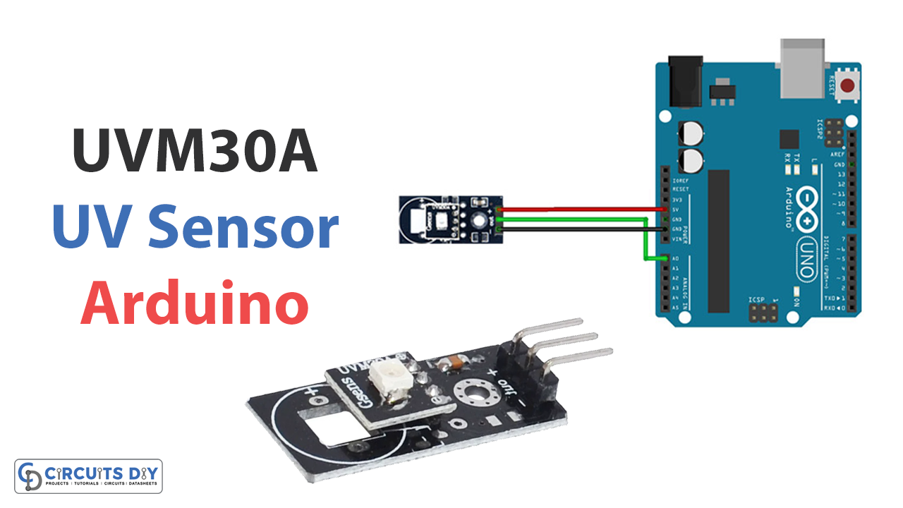
Are you looking for a way to measure UV radiation levels in your environment? Look no further than the UVM30A UV sensor module, which can easily be interfaced with an Arduino microcontroller. This sensor module is affordable and compact and provides highly accurate measurements in a wide range of UV radiation levels.
In this article, we will explore how to set up and interface the UVM30A with an Arduino and interpret and use the sensor data. Whether you’re a scientist, hobbyist, or just curious about UV radiation levels, this sensor module, and Arduino combination is a powerful tool for measuring and understanding UV radiation.
What is UVM30A UV Sensor Module?
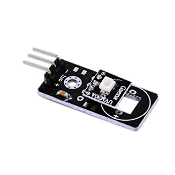
The UVM30A UV sensor module is a device that measures how much UV light reaches the sensor’s surface. The UV light intensity is then converted into a change in the analog output of this module. UV or ultra-violet light is created by the sun. The gradual depletion of Earth’s ozone layer has led to an increase in harmful ultraviolet (UV) radiation, increasing the risk of sunburn and other symptoms of overexposure.
Hence, It is necessary to have a method that can detect or measure the intensity of UV radiation. Ultraviolet (UV) radiation sensors like UVM30A are used because this kind of radiation is invisible to the naked eye. They can detect low-level UV radiation both in and out of doors. The usage of UV sensors is widespread. Pharmaceuticals, autos, and robots are only a few examples.
Hardware Components
You will require the following hardware for Interfacing UVM30A UV Sensor Module with Arduino.
| S.no | Component | Value | Qty |
|---|---|---|---|
| 1. | Arduino UNO | – | 1 |
| 2. | UV Sensor Module | UVM30A | 1 |
| 3. | Breadboard | – | 1 |
| 4. | Jumper Wires | – | 1 |
UVM30A UV Sensor with Arduino
Now that you have got an idea about the module and its working, it’s time to interface the circuit. Hence, for that, you need to follow the given steps:
Schematic
Make connections according to the circuit diagram given below.
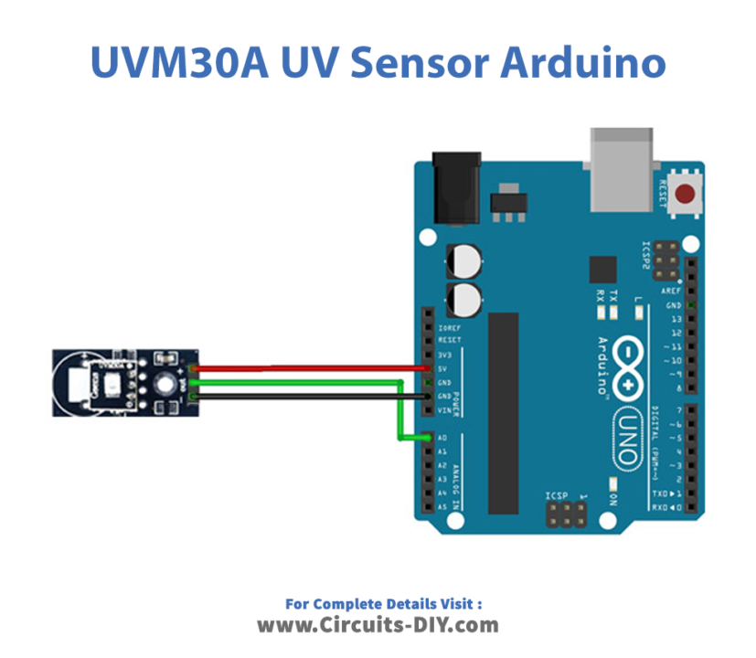
Wiring / Connections
| Arduino | UV Sensor Module |
|---|---|
| 5V | VCC |
| GND | GND |
| A0 | OUT |
Installing Arduino IDE
First, you need to install Arduino IDE Software from its official website Arduino. Here is a simple step-by-step guide on “How to install Arduino IDE“.
Code
Now copy the following code and upload it to Arduino IDE Software.
void setup(){
  Serial.begin(9600);
}

void loop()
{
  int sensorValue;

 sensorValue=analogRead(A0);
 Serial.print("The voltage value:");
 Serial.print(sensorValue*5000/1023.0);
 Serial.println("mV");
 delay(1000);
 Serial.print("\n");
}
Let’s Test It
It’s time to test the circuit once you upload the code. As the Arduino gets the power, the code will cause the Arduino to continuously read the voltage on analog pin 0 and print it out in mV.
Working Explanation
It is the coding that allows the circuit to function. So here’s the code explanation:
- In the void setup, Serial.begin(9600) sets up serial communication with a baud rate of 9600 bits per second.
- In the void loop, the code starts by declaring the variables used in the program. The variable is an integer called sensorValue, which will store the voltage value of a sensor connected to analog pin A0.
- The loop() function reads the value from analog pin A0 and stores it in a variable called sensorValue.
- Then, Serial.print(“The voltage value:”); prints out text on the screen. Serial.print(sensorValue*5000/1023.0) prints the calculated value before printing out “mV” for millivolts and then waiting 1 second before taking the next reading.
Applications
- Automation systems, etc
- Pharmaceuticals
- Automobiles
- Robotics.
- Printing industry
Conclusion.
We hope you have found this Interfacing UVM30A UV Sensor Module with Arduino Circuit very useful. If you feel any difficulty making it feel free to ask anything in the comment section.
Related posts:
 Ultrasonic Range Detector Using Arduino and SR-04F
 How to make Door Sensor using Arduino
 Connect Two Arduino Boards Using I2C Communication Protocol
 Display Temperature from LM35 Sensor on OLED - Arduino Tutorial
 How to Interface PIR Motion Sensor with Arduino UNO
 How to Interface Mini SD Card Module with Arduino UNO