Introduction
A LDR analog threshold controlled 5V SPDT Relay using an Arduino UNO microcontroller is a system that uses a Light Dependent Resistor (LDR) to sense the ambient light level and a Single Pole Double Throw (SPDT) relay to switch an external load based on the ambient light level. The LDR is connected to an analog input of the Arduino UNO microcontroller, which reads the resistance of the LDR and converts it to a digital value using the analogRead() function. The digital value is then compared with a threshold value, if the value is below the threshold, the relay is turned on, if not it will be turned off.
A Light-dependent resistor (LDR) is a type of resistor whose resistance changes based on the amount of light that falls on it. It is also known as a photoresistor. LDRs are made of semiconductor materials such as cadmium sulfide (CdS) or cadmium selenide (CdSe) which exhibit a change in electrical resistance when exposed to light. When there is more light falling on the LDR, its resistance decreases, and when there is less light, its resistance increases.
Hardware Components
You will require the following hardware for Light Sensor Triggers Relay Circuit.
| S.no | Component | Value | Qty |
|---|---|---|---|
| 1. | Arduino UNO | – | 1 |
| 2. | USB Cable Type A to B | – | 1 |
| 3. | Light Sensor | – | 1 |
| 4. | Relay | – | 1 |
| 5. | Power Adapter | 12V | 1 |
| 6. | DC Power Jack | – | 1 |
| 7. | Power Adapter for Arduino | 9V | 1 |
| 8. | Warning Light Bright Waterproof | – | 1 |
| 9. | Resistor | 10KΩ | 1 |
| 10. | Breadboard | – | 1 |
| 11. | Jumper Wires | – | 1 |
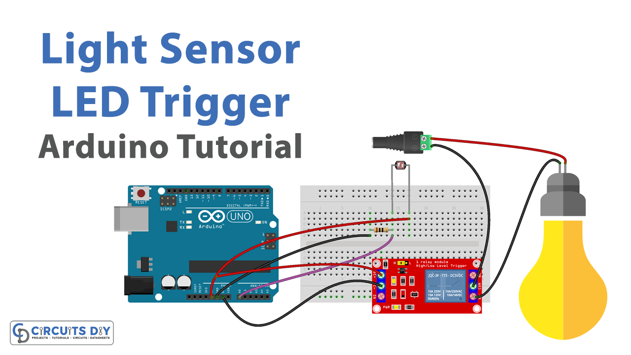
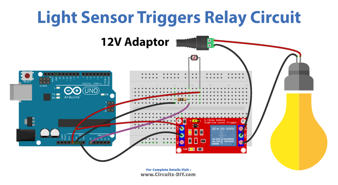
Light Sensor Triggers Relay with Arduino
- Connect the LDR to the Arduino using the analog pin specified in the LDR’s documentation. Connect the SPDT relay to the Arduino using the digital pin specified in the relay’s documentation.
- In the Arduino IDE, create variables to store the LDR’s analog value and the relay’s state:
int ldrValue = 0;
int relayState = 0;
- In the setup() function, initialize the serial communication and set the relay pin as an output:
Serial.begin(9600);
pinMode(relayPin, OUTPUT);
- In the loop() function, read the analog value from the LDR using the analogRead() function:
ldrValue = analogRead(ldrPin);
- Compare the LDR value with a threshold value and set the relay state accordingly:
if (ldrValue < thresholdValue) {
  relayState = 1;
} else {
  relayState = 0;
}
- Write the relay state to the relay pin using the digitalWrite() function:
digitalWrite(relayPin, relayState);
- Send the relay state to the serial monitor using the Serial.println() function:
Serial.println(relayState);Schematic
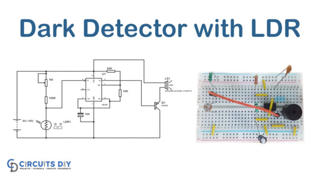
Make connections according to the circuit diagram given below.
Installing Arduino IDE
First, you need to install Arduino IDE Software from its official website Arduino. Here is a simple step-by-step guide on “How to install Arduino IDE“.
Code
Now copy the following code and upload it to Arduino IDE Software.
const int LIGHT_SENSOR_PIN = A0; // Arduino pin connected to light sensor's  pin
const int RELAY_PIN        = 3;  // Arduino pin connected to Relay's pin
const int ANALOG_THRESHOLD = 500;

// variables will change:
int analogValue;

void setup() {
  pinMode(RELAY_PIN, OUTPUT); // set arduino pin to output mode
}

void loop() {
  analogValue = analogRead(LIGHT_SENSOR_PIN); // read the input on analog pin

  if(analogValue < ANALOG_THRESHOLD)
    digitalWrite(RELAY_PIN, HIGH); // turn on Relay
  else
    digitalWrite(RELAY_PIN, LOW);  // turn off Relay
}
Working Explanation
In the setup() function, the Arduino code configures the pin modes for the LDR and the relay and starts the serial communication at a specific baud rate. The LDR is connected to an analog pin such as A0, this pin is configured as an input to read the value of the LDR. The relay is connected to a digital pin such as D12, this pin is configured as an output to control the relay.
In the loop() function, Arduino code continuously reads the analog value of the LDR and compares it to a threshold value that is set in the code. The threshold value is set based on the requirement and the LDR. The value read by the LDR can be affected by the ambient light and the threshold should be set accordingly.
If the value read from the LDR is less than the threshold, it means the ambient light is low, so it will turn on the relay and send “Relay is ON” to the serial monitor. If the value is greater than or equal to the threshold, it means the ambient light is high, so it will turn off the relay and send “Relay is OFF” to the serial monitor.
Applications
- Automatic lighting control
- Street lighting control
- Automatic window blinds control
- Automated greenhouse control
- Photography equipment
Conclusion.
We hope you have found this Light Sensor Triggers Relay Circuit very useful. If you feel any difficulty in making it feel free to ask anything in the comment section.