Introduction
Have you noticed that the lights switch on when you walk or be there in many places in today’s world? Motion detection sensors are used in these locations. The PIR motion detection sensor is one of the most common and affordable sensors for this purpose. It’s a low-powered Passive infrared sensor commonly used in security and automated lighting systems. It notifies you of the movement but does not provide information about who moved. Passive infrared detectors are another name for it. This article is about PIR Motion Sensor Switch. Thus, we will utilize this sensor to make a burger alarm.
There are two slots in the PIR sensor. When there is no movement, the readings in both slots are the same. It inspects the heat and identifies activity when any warm body or human is present. This results in a difference between the two slots. The output load then begins to work.

This Project is sponsored by PCBWay. They have an open-source community, people can share their design projects with each other. Moreover, every time people place an order for your board, PCBWay will donate 10% of the cost of PCB to you, for your contribution to the Open Source Community.
Hardware Components
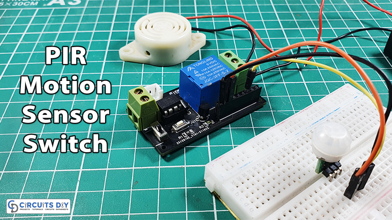
The following components are required to make PIR Motion Sensor Switch Circuit
| S.no | Component | Value | Qty |
|---|---|---|---|
| 1. | PIR Motion Sensor | – | 1 |
| 2. | controller IC | Attiny85 | 1 |
| 3. | Relay switch | – | 1 |
| 4. | Lamp | 220V | 1 |
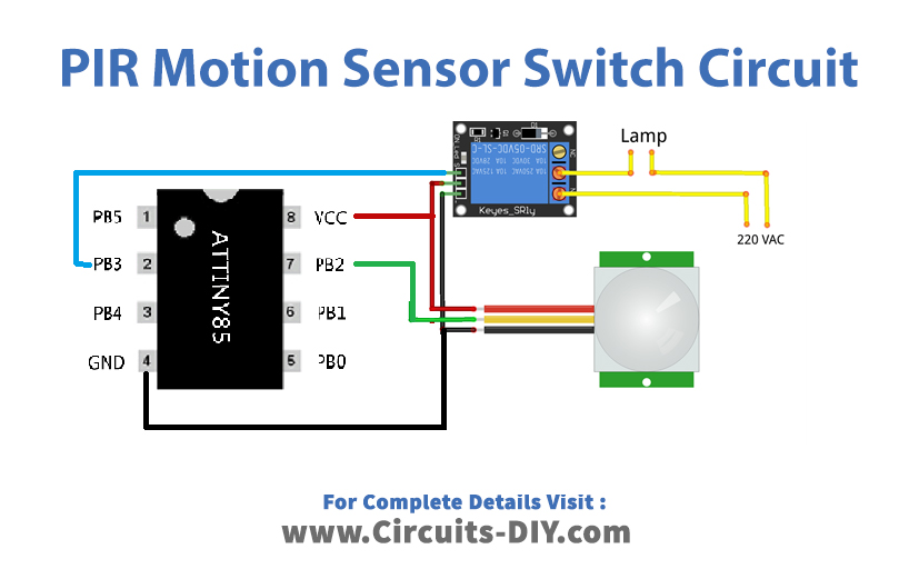
PIR Motion Sensor Switch Circuit
Code
int sensorPin = 2;          // Set up a PIR sensor pin
int pirState = LOW;
int val = 0;
int relayPin = 3;           //Set up a Relay pin

void setup() {
pinMode(sensorPin, INPUT);
pinMode(relayPin, OUTPUT);
//Serial.begin(9600);
}

void loop() {
val = digitalRead(sensorPin);  // read input value
if (val == HIGH) {            // check if the input is HIGH
digitalWrite(relayPin, HIGH);  // turn Relay ON
delay(150);

if (pirState == LOW) {
//Serial.println("Motion detected!");
pirState = HIGH;
}
} else {
digitalWrite(relayPin, LOW); // turn Relay OFF
delay(150);
if (pirState == HIGH) {
//Serial.println("Motion ended!");
pirState = LOW;
}
}
}
Working Explanation
According to the diagram provided above, connect the PIR motion sensor switch to the Attiny85. In the Arduino IDE, write the code. Using Arduino, burn or upload the code to the controller. If someone walks by this sensor, the controller IC will read the value of the sensor and activate the relay, which will turn on the lamp. The message is also shown on the Serial monitor.
Code Explanation
- The code first has described the PINs of an Arduino at which the relay and sensor are connected. It also defines the PirState variable that keeps track of the status of the sensor using the int. And, add the variable val that holds the data coming from the sensor.
- In the void setup, it has been defined that really is an output and the sensor is an input device
- In the void loop, it has been defined that the controller first read the sensor. If the value of the sensor would high, the output relay would be high. Now, the code will check the status of the sensor. Since the initial status was low, therefore it reads and prints on the Serial monitor that Motion Detected!, and then the code makes its status high. When the human body leaves the digital PIR range, the else loop starts working, and the LED will turn OFF. Seeing the state, the Serial monitor will print Motion Ended!
Application and Uses
- The circuit can be utilized in alarm circuits, like burglar, intruder alarms, etc.
- This circuit can also help to save electricity.