Introduction
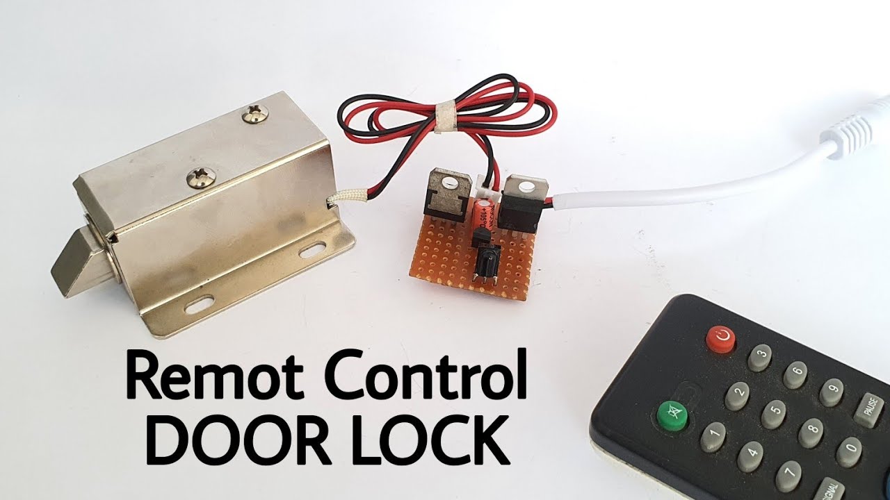
Security is an important task to work on in any place. Whether, industries, banks, museums, or homes, it’s important to make every place secure. So, today in this tutorial, we are making a Remote control Door Lock Circuit for safety purposes. Remote Control Door Locks allow Wireless Control. This means one can unlock or lock their doors with just one click from their smartphone or remote control. It replaces the traditional lock system and provides a modern lock that is way more secure.
For the making of this circuit, only one transistor will be used. We are also using the electromagnetic door lock. The Magnetic locks use electromagnetism to deal with the entire locking mechanism. The circuit is easy to build and simple to use requiring few electronic components.
JLCPCB is the foremost PCB prototype & manufacturing company in china, providing us with the best service we have ever experienced regarding (Quality, Price Service & Time).
Hardware Components
The following components are required to make the Remote Control Door Lock Circuit
| S.no | Component | Value | Qty |
|---|---|---|---|
| 1. | Electromagnetic lock | – | 1 |
| 2. | Voltage Regulator IC | 7805 | 1 |
| 3. | Transistor | BC547 | 1 |
| 4. | NPN Transistor | T1p31 | 1 |
| 5. | Electrolytic Capacitor | 22uf | 1 |
| 6. | IR receiver | 1 | |
| 7. | Power supply | 12V | 1 |
BC547 Pinout

For a detailed description of pinout, dimension features, and specifications download the datasheet of BC547
7805 Pinout
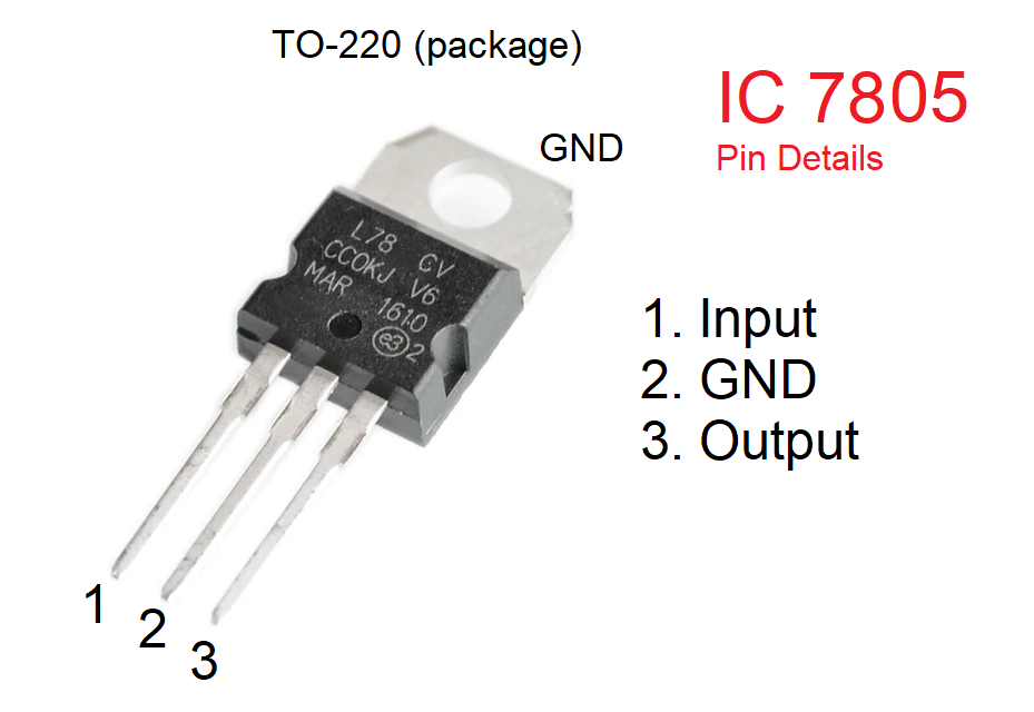
For a detailed description of pinout, dimension features, and specifications download the datasheet 7805
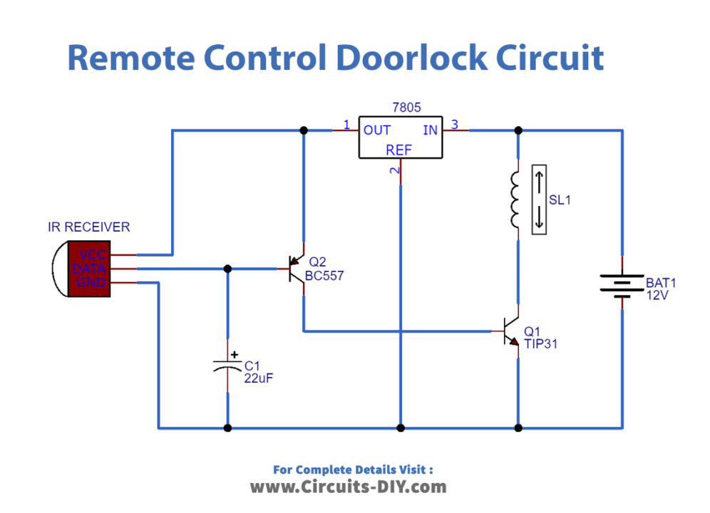
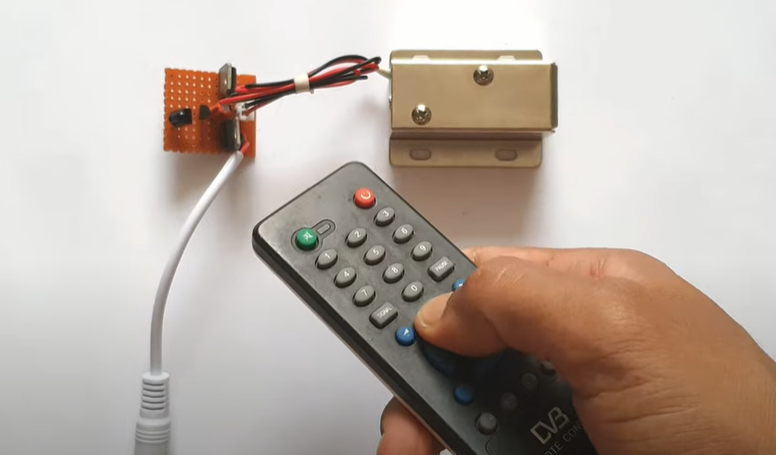
Remote Control Door Lock Circuit
Useful Steps
- Connect the regulator IC, T1P31 transistor, and BC577 transistor in a way that the collector pin of the BC557 transistor goes to the base of t1p31 and emitter to the output pin of the regulator IC.
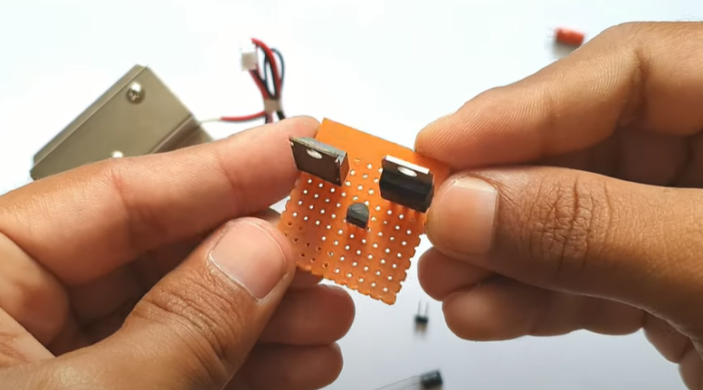
- Connect the negative pin of the capacitor on the emitter of T1P31 and circuit ground and positive to the base pin of BC557
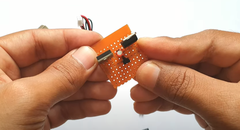
- Place an IR receiver and connect its VCC pin to VCC, ground to ground, and data pin to the base pin of BC557.
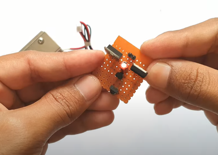
- Provide 12V Dc input, positive on the input pin of 7805 and negative to the emitter of T1P31. Output is coming from the 7805 input pin and collector of T1P31.
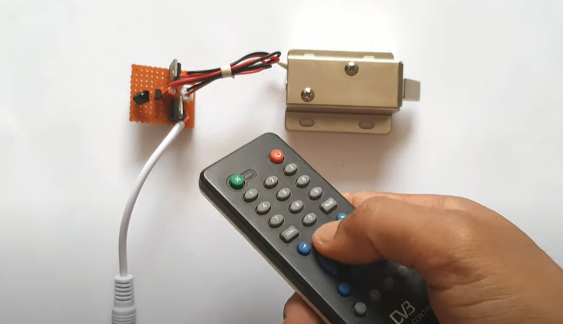
Working Explanation
Magnetic locks use electromagnetism to handle the entire locking mechanism. When we press the button of the remote, the circuit works, and the magnet inside the door lock gets energized, it then connects to the armature and locks the door. To allow access or egress, we must provide a switch to de-energize the magnet. As the electric power turns on the magnet, the bolt locks the door.
Applications
- We can use it in industries, homes, and offices for security purposes.
- Safety devices.
- Home automation system