A PCB or Printed Circuit Board is a thin electronic board that serves as a vital platform for organizing electronic circuits. A PCB is usually made out of fiberglass, epoxy, or other various laminated materials, with a conductive pathway, etched onto the board to connect different components together. PCBs, serve as the foundation for technology size reduction in many electronic & electrical machines. So, in today’s article, we are going to go over a list of the Top 5 Best PCB Projects covered on this platform. This list contains a combination of top tier tested PCB projects, designed for beginners to electronics.
While sorting out the projects for this article, we have taken care to serve you with the most popular DIY PCB projects on our website. So, the following are our Top 5 Best PCB Projects For Beginners.
PCBWay is Providing a Quality PCB Prototype and Manufacturing Service ..We Highly Recommended to Order PCB’s from PCBWay

To Buy Custom built PCB’s at Low prices please visit: www.pcbway.com
1) Fridge Door Alarm
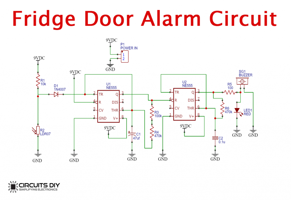
A Fridge door Alarm is a simple PCB project designed to detect & inform the status of any refrigeration unit’s door: whether its open or not. It produces a monotonous beeping noise if the fridge door is left open for too long by an accident. It’s common use is in refrigerators, Temperature Controlled Freezers & beverage coolers.
Hardware Components
You will need the following parts to build this project
Circuit Diagram of PCB
Circuit Operation
The operation of this circuit is based on the simultaneous communication between two NE555 IC’s. IC1 evaluates & corresponds with the input of the LDR while IC2 uses the output sent from IC1 to regulate the buzzer as per the position of the fridge door.
2) DIY Clap Switch Circuit
Clap switch circuit is a simple electronic circuit that makes use of the application of dynamic control of appliances by using sound. It is a very basic, easy to understand & relatively inexpensive to create. Clap switches are commonly used with DC light fixtures to be controlled by using sound.
Hardware Components
You will need the following parts to build this project.
Circuit Diagram of PCB

Circuit Operation
The heart of this circuit is a CD4)17 IC. An audio signal is received by the mic. which is then fed to the CD4017 IC through a series of transistors. which then triggers a 5V SPDT relay to trigger a LED light.
3) Music Reactive LED Circuit
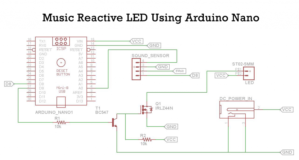
The music reactive led circuit is a simple electronic circuit that responds to the varying rhythmic changes in the intensity level of any musical device. They are a perfect starting point for people completely new to the concept of PCBs. They are usually working for decorative purposes.
Hardware Components
You will need the following parts to build this project.
Circuit Diagram of PCB
Circuit Operation
An AC audio Signal acts as input by the KY – 038 sound sensor module. The module feeds the analog out at pin A0 of the controller & the digital out to pin D8 of the micro-controller. When D9 goes high, the output DC signal acts as a control signal to the base of the BC547 transistor. The Drain output of the transistor then triggers the LED strip
4) Electronic Piano PCB
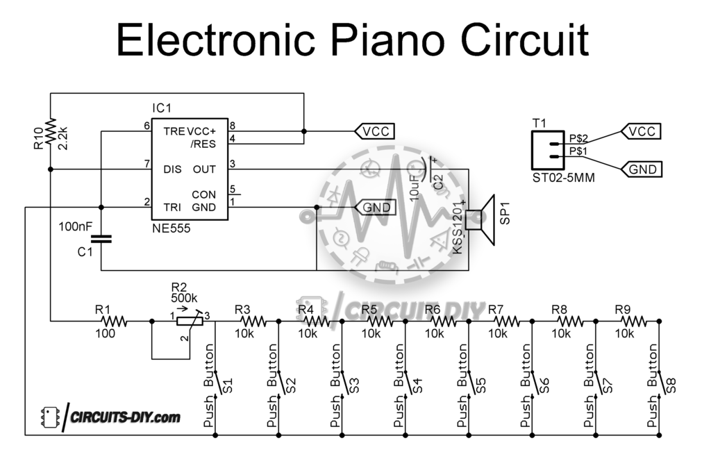
On No. 4 in our list of top 5 Best PCB Projects comes the electronic piano PCB circuit. The electronic piano PCB is a simple PCB based project that produces a melodic sound with the press of each button. Its most common application is in devices such as musical toys doorbells & alarms. It is a cheap, easy to build & educative project for beginners to PCB.
Hardware Components
You will need the following parts to build this project.
Circuit Diagram of PCB
Circuit Operation
The circuit operation of this circuit is very simple. 8 pushbuttons generate & feed 8 different kinds of tone with an audible range of 20Hz to 20KHz to an adjoined speaker. On pressing the first button from right it produces a high pitch tone. On pressing the last button it delivers a low pitch tone.
5) Call Detector Circuit
A simple PCB based circuit that can detect the presence of any transmitting RF mobile device nearby & can provide alerts with respect to it. This PCB circuit generally depicts a Frequency Detector or a Current to Voltage Converter Circuit. It mainly acts as a contingent device against smartphones in places where smartphones shouldn’t be brought such as exam halls & military installations.
Hardware Components
You will need the following parts to build this project.
Circuit Diagram of PCB
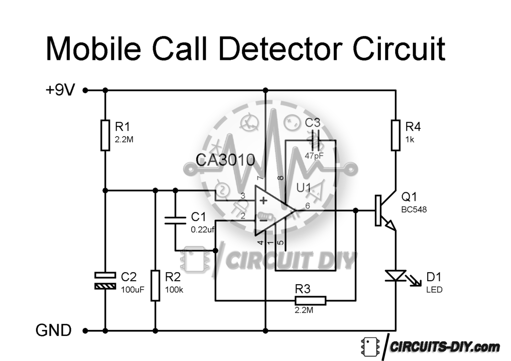
Circuit Operation
The working of this circuit is pretty simple. The 0.22uF capacitor leads act as a GHz loop antenna to capture any RF signal from any nearby transmitting device such as a cell phone. When a cell phone signal is detected, the output of the CA3130 IC goes high and low back & forth according to the frequency of the signal as indicated by the LED.