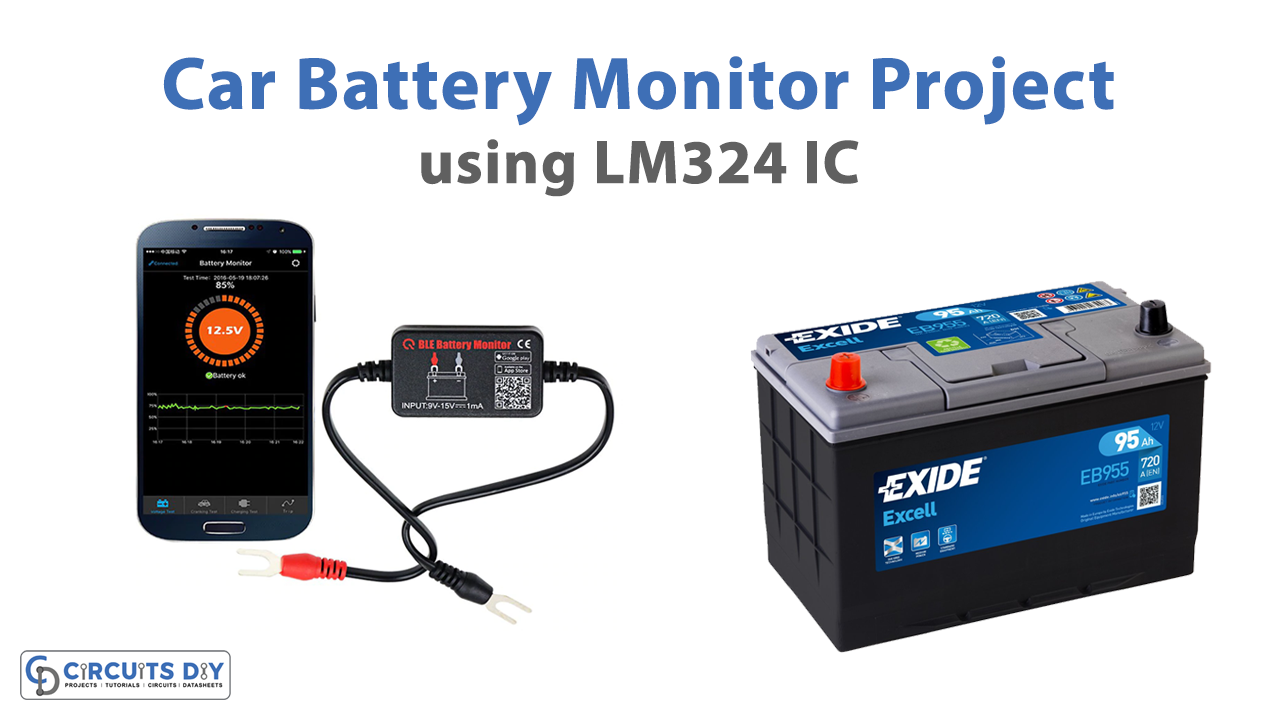
In this tutorial, we are making a project on a Car Battery Monitor With Low Battery Cutoff Function. This circuit monitors the battery of any vehicle and shows a visual indication of the battery level through the four LEDs. It also contains a low battery cutoff function. This function will disconnect the vehicle’s battery with an electrical appliance when its battery level is at 50%, this will save it from deep/full discharge.
This circuit will automatically disconnect the battery from the headlights in case you forgot to switch them off. Other than headlights you can use any lights or appliances of your car through the relay in this circuit. They will be deactivated automatically when the battery level falls to 50%.
Hardware Components
The following components are required to make a Car Battery Monitor Circuit
| S.no | Components | Value | Qty |
|---|---|---|---|
| 1. | Battery | – | 1 |
| 2. | IC | LM324 | 1 |
| 3. | LED | – | 4 |
| 4. | Resistor | 10K, 1K | 1, 4 |
| 5. | Zener diode | 3V | 1 |
| 6. | Relay | – | 1 |
| 7. | Diode | 1N4007 | 1 |
| 8. | Transistor | 2N4401 | 1 |
| 9. | Variable Resistor | 10K | 4 |
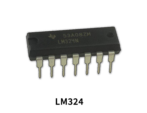
LM324 Pinout
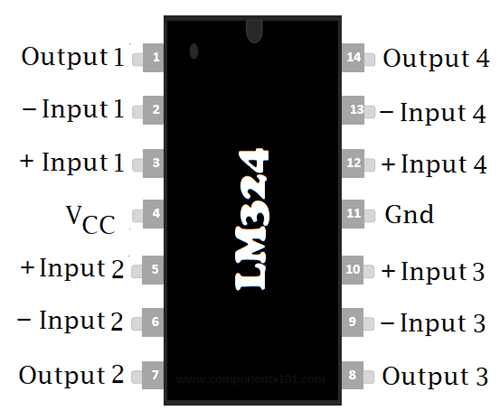
For a detailed description of pinout, dimension features, and specifications download the datasheet of LM324
Car Battery Monitor Circuit
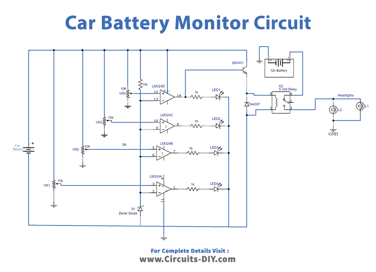
Working Explanation
We are using an LM324 IC. This IC has four independent operational amplifiers. All of these are working as a separate comparators in this circuit to detect the specific voltage level of the battery. These voltage levels are set through variable resistors of 10K. Each op-amp has a variable resistor connected to its input. LEDs are used for visual indication of battery levels.
Circuit tuning
- Take a variable power supply and set 12.5V because a 12V battery shows 12.5V in DMM when fully charged.
- Connect this power supply in the place of the battery in the circuit.
- Adjust VR1 until LED1 turns off.
- Change the voltage of the power supply to 12.3V and adjust the VR2 until LED2 turns off.
- Change the voltage of the power supply to 12.2 now and again adjust the VR3 until LED3 turns off.
- Now for the last level set 12V in the power supply and adjust VR4 until LED4 turns off. At this point, the transistor will turn off too and deactivates the relay which is connected with the battery and the headlights.
Applications and uses
This circuit can be used with any device of a battery system of 12V like UPS, solar system, etc.