Introduction
In this tutorial, we are going to Make the “LSM303 Triple-Axis Accelerometer Magnetometer Module with Arduino”.
A magnetometer, often known as a compass, is a type of navigation equipment that evaluates the strength of the magnetic field or the magnetic dipole moment. A magnetometer is a device containing a sensor that detects magnetic flux density. Magnetometers measure a magnetic field’s direction, strength, or relative fluctuation at a specific area. Magnetometers are often used to calibrate electromagnets & permanent magnets as well as to determine the magnetism of a substance.
The accelerometer measures the vibration of any object. Practically, the vibrations of any object cause the piezoelectric effect. Thus, it converts the mechanical motions into an electrical signal. An accelerometer converts mechanical energy into electrical energy
Brief Overview of the LSM303 Module
ST Electronics’ LSM303 is a full system-in-package module. The module is a compact, high-performance, equipped with a triple-axis accelerometer that measures an object’s tilt angle or movement with respect to the Earth. It is also equipped with a magnetometer, which measures magnetic strength to determine the orientation of an item. The module is compatible and communicates via the I2C interface.
Features of LSM303
- 3 magnetic field channels and 3 acceleration channels
- From ±1.3 to ±8.1 Gauss magnetic field full scale
- ±2g/±4g/±8g/±16g linear acceleration full scale
- 16-bit data output
- I²C serial interface
- Analog supply voltage 2.16 V to 3.6 V
- Power-down mode / low-power mode
- 2 independent programmable interrupt generators for free-fall and motion detection
- Embedded temperature sensor
- Embedded FIFO
- 6D/4D-orientation detection
Pinouts of LSM303
| Pin Name | Description |
| SCL | Signal interface I²C serial clock (SCL) |
| SDA | Signal interface I²C serial data (SDA) |
| I2 | Inertial interrupt 2, out pin |
| I1 | Inertial interrupt 1, out pin |
| DRDY | Data ready out pin |
| GND | Ground pin |
| Vin | Power pin (3.3v ~ 5v) |
| 3.3v | 3.3v Power out pin for other peripherals. |
Hardware Required
| S.no | Components | Value | Qty |
|---|---|---|---|
| 1 | Arduino UNO | – | 1 |
| 2 | USB Cable Type A to B | – | 1 |
| 3 | Triple-Axis Accelerometer Magnetometer | LSM303 | 1 |
| 4 | Jumper Wires | – | – |
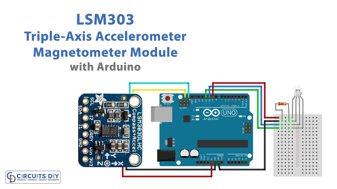
Circuit Diagram

Connection Table
| Arduino UNO | LSM303 |
|---|---|
| GND | GND |
| 5v | Vcc |
| SDA | SDA |
| SCL | SCL |
Arduino Code
#include <Wire.h>
#include <Adafruit_Sensor.h>
#include <Adafruit_LSM303_U.h>


/* Assign a unique ID to this sensor at the same time */
Adafruit_LSM303_Mag_Unified mag = Adafruit_LSM303_Mag_Unified(12345);


// OUTPUT: Use digital pins 9-11, the Pulse-width Modulation (PWM) pins
// LED's cathodes should be connected to digital GND
int redPin = 9;   // Red LED,   connected to digital pin 9
int grnPin = 10;  // Green LED, connected to digital pin 10
int bluPin = 11;  // Blue LED,  connected to digital pin 11


// Program variables
int redVal = 0;   // Variables to store the values to send to the pins
int grnVal = 0;
int bluVal = 0;

int magnetometer = 0;
int magVal = 0; //Variable to store the input from the magnetometer


// Pi for calculations - not the raspberry type
const float Pi = 3.14159;

// This is the desired direction of travel
// expressed as a 0-360 degree compass heading
// 0.0 = North
// 90.0 = East
// 180.0 = South
// 270 = West
const float targetHeading = 0.0;


void setup()

{

  Serial.begin(9600);
  Serial.println("Magnetometer Test"); Serial.println("");

  /* Initialise the sensor */
  if(!mag.begin())
  {
    /* There was a problem detecting the LSM303 ... check your connections */
    Serial.println("Ooops, no LSM303 detected ... Check your wiring!");
    while(1);
  }

  pinMode(redPin, OUTPUT);   // sets the pins as output
  pinMode(grnPin, OUTPUT);
  pinMode(bluPin, OUTPUT);

}


void loop(void)

{ /* Get a new sensor event */
  sensors_event_t event;
  mag.getEvent(&event);


  // Calculate the angle of the vector y,x
  float heading = (atan2(event.magnetic.y,event.magnetic.x) * 180) / Pi;  // Normalize to 0-360


  if (heading < 0)

  { heading = 360 + heading;
  }


  magVal = heading;  // read the magnetometer

  Serial.print("mag: "); Serial.print(magVal); Serial.print(" # ");


  if (magVal < 91)  // Lowest fourth of the magnetometer's range (0-90)

  { magVal = (magVal * 3) / 4; // Normalize to 0-68

    redVal = 69 - magVal;  // Red from full to off
    grnVal = magVal;        // Green from off to full
    bluVal = 1;             // Blue off

    Serial.print("1: "); Serial.print(redVal); Serial.print(":");Serial.print(grnVal);
    Serial.print(":"); Serial.println(bluVal);
  }


  else if (magVal < 181) // Lower middle fourth of magnetometer's range (91-180)

  { magVal = ( (magVal-91) * 3) / 4; // Normalize to 0-68

    redVal = 1;            // Red off
    grnVal = 69 - magVal; // Green from full to off
    bluVal = magVal;       // Blue from off to full

    Serial.print("2: "); Serial.print(redVal); Serial.print(":");Serial.print(grnVal);
    Serial.print(":"); Serial.println(bluVal);
  }


  else if (magVal < 271)// Upper middle fourth of magnetometer"s range (181-270)

  { magVal = ( (magVal-182) * 3) / 4; // Normalize to 0-68

    redVal = 1;           // Red off
    grnVal = 1;            // Green off
    bluVal = 69 - magVal; // Blue from full to off

    Serial.print("3: "); Serial.print(redVal); Serial.print(":");Serial.print(grnVal);
    Serial.print(":"); Serial.println(bluVal);
  }


  else  // Upper fourth of magnetometer"s range (271-360)

  { magVal = ( (magVal-272) * 3) / 4; // Normalize to 0-68

    redVal = 1;       // Red of
    grnVal = 1;       // Green off
    bluVal = 1;       // Blue off

    Serial.print("4: "); Serial.print(redVal); Serial.print(":");Serial.print(grnVal);
    Serial.print(":"); Serial.println(bluVal);
  }


  analogWrite(redPin, redVal);   // Write values to LED pins
  analogWrite(grnPin, grnVal);
  analogWrite(bluPin, bluVal);

}
Working Explanation
In this circuit, we are interfacing LSM303 Triple-Axis Accelerometer Magnetometer Module with Arduino. For this, connect the Arduino to the computer and upload the code. According to the execution, the serial monitor and RGB LED would show the magnetic values, RGB values, and colors, accordingly. Move the module to see how the color changes. Thus, it is the compass, which displays direction using a basic RGB LED.
Code Explanation
- First, we have included the required libraries. Then Give the specific ID in object Adafruit_LSM303_Mag_Unified mag. Then define the variables that define the pins at which the output is connected. Then define the program Variables for storing the values to be sent to the pins. The magVal is that variable that stores the values coming from the magnetometer.
- In the void setup, use serial print to print something like a magnetometer test (since here we are testing the sensor). Now five are the conditions for detecting the LSM303. Next, declared the previously defined pins as output.
- In a void loop, use function mag.getEvent(&event to get a new sensor event. Then, define the formula that calculates the angle. and store it in the float variable heading. Now give conditions. The function magVal now always has the heading value, because we have written magVal = heading. Now define the ranges and accordingly turns on/off the LEDs. Use the analogWrite function to write values to LED pins.
Application and Uses
- Position detection on a rotating map
- Detection of free fall
- Intelligent power management for mobile devices
- Orientation of the display
- Input devices for gaming and virtual reality
- Impact detection and recording
- Monitoring and correction for vibration