Introduction
A circuit that detects darkness or the absence of light is known as a darkness detector or dark detector. We can create different night light sensor Dark Detector electronics projects by employing the most basic components like LDR, 555 timer IC, etc. Thus, there are different ways to make dark sensors which we will discuss in this article.
However, the issue remains: when do we require a dark-sensing detector? See, we humans are working hard every day to create an automated world; we prefer not to waste our time on trivial matters that divert our attention away from more important tasks. Take, for example, street lights; manually turning on those lights necessitates someone performing that task every day. On the other side, if we automate this process by employing a dark sensor that detects darkness and switches on automatically, we would save time.
PCBWay commits to meeting the needs of its customers from different industries in terms of quality, delivery, cost-effectiveness, and any other demanding requests. As one of the most experienced PCB manufacturers in China. PCBWay gives diverse options for customers to design their own PCBs. For example, more options for solder masks like red, yellow, blue, purple, pink, orange and transparent, and so on. They also have mature mechanisms of return or refund if any problem is caused by PCBWay.

- So Visit their website first -> PCBWay.com
- Register / Signup for New Account
- Upload your Gerber files
- Select Specifications like Quantity, Color, Dimensions &, etc
- Finally, Place your Order
Hardware Components
| S.no | Component | Value | Qty |
|---|---|---|---|
| 1. | LDR | – | 1 |
| 2. | Transistor | BC547 | 2 |
| 3. | Potentiometer | 10KΩ | 1 |
| 4. | Buzzer | – | 1 |
| 5. | Resistor | 100Ω, 1K | 1 |
| 6. | Diode | 1N4007 | 1 |
| 7. | Battery | 9v | 1 |
| 8. | LED | – | 1 |
| 9. | Relay | 5V | 1 |
BC547 Pinout

For a detailed description of pinout, dimension features, and specifications download the datasheet of BC547
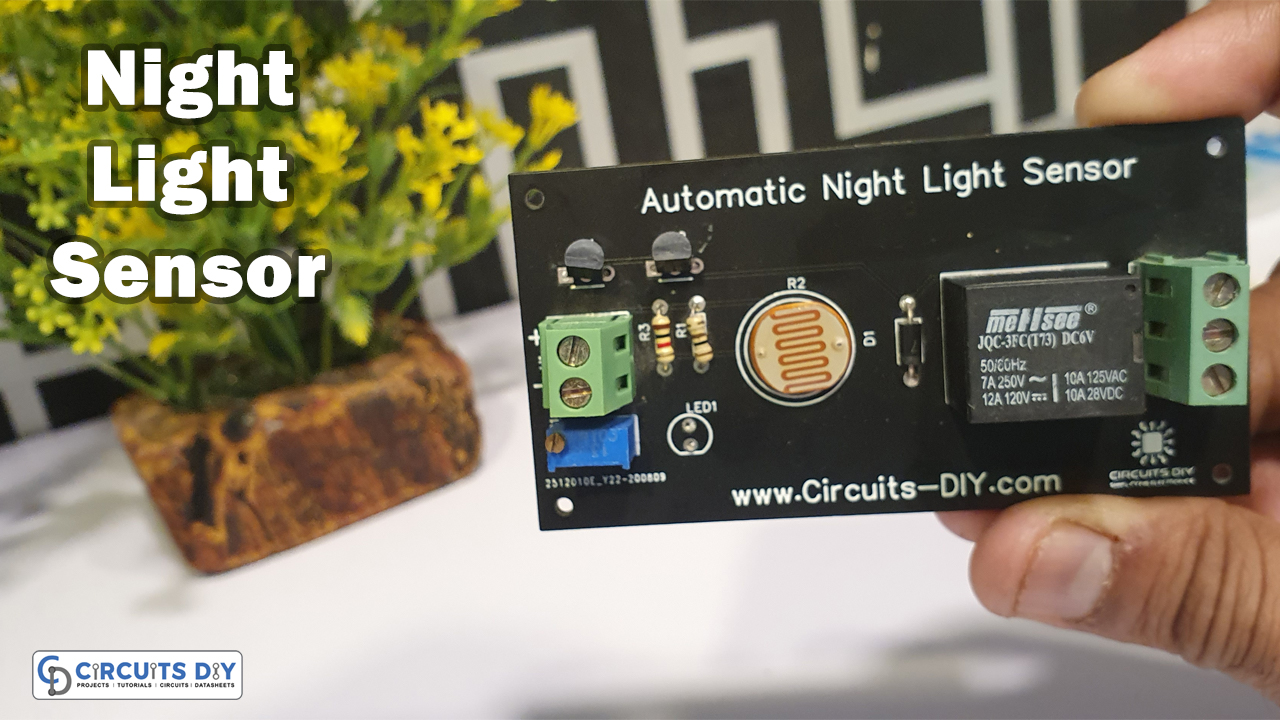
Night Light Sensor Project
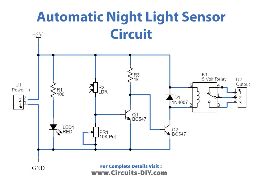
Working Explanation
This circuit also uses the LDR. So, When there is no light, the light-dependent resistor works. In normal circumstances, when there is light, the circuit’s resistance prevents the electric current from flowing. When night falls and LDR is exposed to the dark, the resistance decreases, letting the current flow. This activates the circuit’s first transistor, which serves as the control signal for the second transistor. The output is sent to the second transistor’s collector, which is used to energize the relay coil. As a result, it turned the relay on.
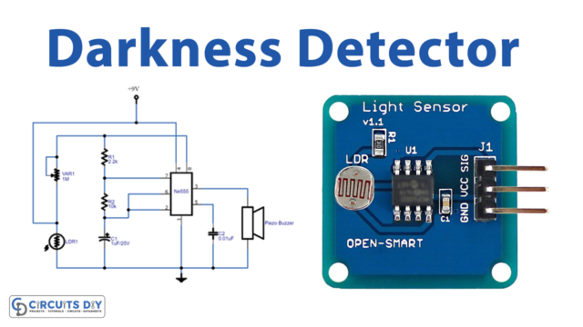
Darkness Detector Circuit Using 555 Timer IC
Hardware Components
| Sr. No | Components | Value | Qty |
|---|---|---|---|
| 1 | LDR | – | 1 |
| 2 | 555 Timer IC | – | 1 |
| 3 | piezo buzzer | – | 1 |
| 4 | Potentiometer | 1MΩ | 1 |
| 5 | Capacitor | 1uF/25V, 0.01uF | 1,1 |
| 6 | Resistor | 2.2KΩ, 10KΩ | 1,1 |
| 7 | Connecting wires | – | – |
| 8 | Battery | 9V | 1 |
| 9 | 2-Pin Connector | – | 1 |
NE555 IC Pinout

For a detailed description of pinout, dimension features, and specifications download the datasheet of 555 Timer
Working Explanation
The 555 timer IC serves as an astable multivibrator circuit in this Darkness detection circuit. The circuit has a variable resistor that allows us to adjust the sensitivity. There is no current flow across the circuit when a continuous light falls on the LDR. The LDR senses the darkness and lowers its resistance if something happens between the light and the LDR. The electricity then flows through the circuit. The buzzer beeps as a result.
Applications and Uses
- We may utilize these types of darkness detector circuits in applications that automatically switch on lights when it becomes dark.
- We may use it as an emergency light in low-light situations.
- It is also accessible for mining employees.