Introduction
Photography enthusiasts are always on the lookout for ways to improve their skills and take better shots. One area that can greatly enhance the quality of their images is camera control. By remotely triggering a camera’s shutter button, photographers can avoid camera shake and achieve sharper, more stable shots. In this context, DIY remote shutter controls have gained popularity among photographers, who seek to customize their devices and have greater control over the process.
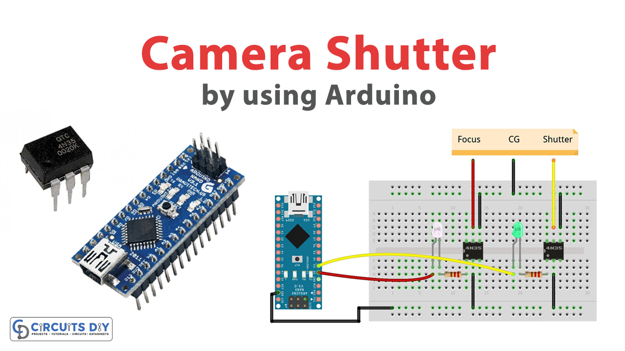
In this article, we will discuss how to create a simple, yet effective, remote shutter control for a Panasonic FZ200 camera using an Arduino and optocouplers, as well as the other necessary components and tools. Whether you are a seasoned photographer or a hobbyist, this guide will provide you with the information you need to build your own remote shutter control and elevate your photography to the next level.
Hardware Components
| Components | Value | Qty |
|---|---|---|
| Arduino Nano | – | 1 |
| IC | 4N35 | 2 |
| LED | Green, White | 1, 1 |
| Resistor | 1kΩ | 2 |
| Breadboard | – | 1 |
| Jumper Wires | – | 1 |
Arduino Code
- Declare and initialize two integer variables, “time” and “incomingByte”, with values of 100 and 0 respectively.
int time = 100;
int incomingByte = 0;
- Declare two constant integer variables, “opto_focus” and “opto_shoot”, with values of 2 and 3 respectively.
const int opto_focus = 2;
const int opto_shoot = 3;
- Define the setup function that will be called once at the beginning of the program. Initialize the serial communication with a baud rate of 115200 and set the “opto_focus” and “opto_shoot” pins as output pins using the pinMode function.
void setup() {
    Serial.begin(115200);
    pinMode(opto_focus, OUTPUT);
    pinMode(opto_shoot, OUTPUT);
}
- Define the loop function that will be called repeatedly in a loop. Check if there is any data available in the Serial buffer using the Serial.available() function. If there is data available, read the incoming byte using the Serial.read() function and store it in the “incomingByte” variable.
void loop() {
    if (Serial.available() > 0) {
        incomingByte = Serial.read();
        // Rest of the code goes here
    }
}
- Use a switch statement to perform different actions based on the received byte. If the byte is ‘f’, set the “opto_focus” pin to HIGH using the digitalWrite function, wait for 300 milliseconds using the delay function, and then set the “opto_focus” pin to LOW using the digitalWrite function.
switch (incomingByte) {
    case 'f':
        digitalWrite(opto_focus, HIGH);
        delay(300);
        digitalWrite(opto_focus, LOW);
        break;
    // Rest of the cases go here
}
- If the byte is ‘s’, set the “opto_shoot” pin to HIGH using the digitalWrite function, wait for 2000 milliseconds using the delay function (100*20), set the “opto_shoot” pin to LOW using the digitalWrite function, wait for 1 millisecond using the delay function, and then loop 36 times to read and discard 36 bytes from the Serial buffer using the Serial.read() function.
case 's':
    digitalWrite(opto_shoot, HIGH);
    delay(100*20);
    digitalWrite(opto_shoot, LOW);
    delay(1);
    for (int i = 0; i < 36; i++) {
        Serial.read();
    }
    break;
- If the received byte is not ‘f’ or ‘s’, set the “time” variable to the received byte multiplied by 100.
default:
    time = incomingByte*100;
    break;
- The loop function will repeat itself until the program is stopped or the board is reset.
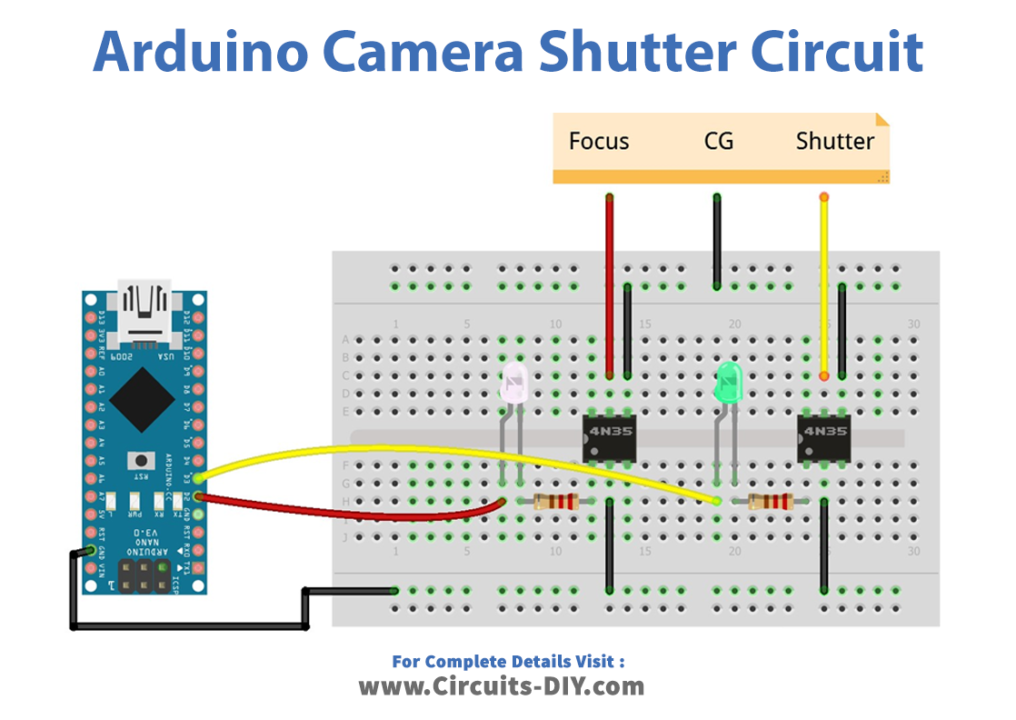
Schematic
Make connections according to the circuit diagram given below.
Installing Arduino IDE
First, you need to install Arduino IDE Software from its official website Arduino. Here is a simple step-by-step guide on “How to install Arduino IDE“.
Code
Now copy the following code and upload it to Arduino IDE Software.
int time    = 100; // Declare and initialize a variable "time" with a value of 100
int incomingByte  = 0; // Declare and initialize a variable "incomingByte" with a value of 0
const int opto_focus = 2; // Declare a constant variable "opto_focus" with a value of 2
const int opto_shoot = 3; // Declare a constant variable "opto_shoot" with a value of 3

void setup()
{
    Serial.begin(115200); // Initialize the serial communication at a baud rate of 115200
    pinMode(opto_focus, OUTPUT); // Set the "opto_focus" pin as an output pin
    pinMode(opto_shoot, OUTPUT); // Set the "opto_shoot" pin as an output pin
}

void loop()
{
    if (Serial.available() > 0) { // Check if there is any data available in the Serial buffer
        incomingByte = Serial.read(); // Read the incoming byte and store it in the "incomingByte" variable

        switch (incomingByte) { // Use a switch statement to perform different actions based on the received byte
            case 'f': // If the byte is 'f'
                digitalWrite(opto_focus, HIGH); // Set the "opto_focus" pin to HIGH
                delay(300); // Wait for 300 milliseconds
                digitalWrite(opto_focus, LOW); // Set the "opto_focus" pin to LOW
                break; // Exit the switch statement

            case 's': // If the byte is 's'
                digitalWrite(opto_shoot, HIGH); // Set the "opto_shoot" pin to HIGH
                delay(100*20); // Wait for 2000 milliseconds (20 times 100 milliseconds)
                digitalWrite(opto_shoot, LOW); // Set the "opto_shoot" pin to LOW
                delay(1); // Wait for 1 millisecond

                for (int i = 0; i < 36; i++) { // Loop 36 times to read and discard 36 bytes from the Serial buffer
                    Serial.read(); // Read a byte from the Serial buffer and discard it
                }
                break; // Exit the switch statement

            default: // If the received byte is not 'f' or 's'
                time = incomingByte*100; // Set the "time" variable to the received byte multiplied by 100
                break; // Exit the switch statement
        }
    }
}
Working Explanation
The code sets up two output pins, opto_focus and opto_shoot, which are used to control a camera’s focus and trigger respectively. In the loop() function, the code checks if there is any data available in the Serial buffer using the Serial.available() function. If there is data available, the code reads the incoming byte using the Serial.read() function and stores it in the incomingByte variable. The code then uses a switch statement to perform different actions based on the received byte. If the byte is ‘f’, the code sets the opto_focus pin to HIGH, waits for 300 milliseconds using the delay() function, and then sets the opto_focus pin to LOW.
If the byte is ‘s’, the code sets the opto_shoot pin to HIGH, waits for a certain amount of time depending on the time variable, and then sets the opto_shoot pin to LOW. The number of times the camera is triggered is determined by the delay() function that follows. Finally, if the received byte is not ‘f’ or ‘s’, the code sets the time variable to the received byte multiplied by 100. This is used to control the duration of the camera trigger.
Applications
- Time-lapse photography
- High-speed photography
- Stop-motion animation
- Remote camera triggering