Introduction
Interfacing an Arduino Dual-axis XY Joystick Module with an Arduino UNO microcontroller involves connecting the joystick module to the microcontroller and using code to control and monitor the movement of the joystick. This allows for the creation of various interactive projects such as controlling a robot, playing games, and more. The Arduino UNO microcontroller provides the processing power needed to receive and interpret signals from the joystick and carry out actions based on the user’s input.
An Arduino dual-axis XY joystick module is a type of input device that provides two-axis control, usually for X and Y positions, to the connected microcontroller. It typically consists of a joystick potentiometer and two push buttons that can be used for various functions such as selecting, zooming, or scrolling. It is often used in projects that require manual input, such as gaming controllers, robotics, and other interactive applications.
Hardware Components
You will require the following hardware for Interfacing Joystick with Arduino.
| S.no | Component | Value | Qty |
|---|---|---|---|
| 1. | Arduino UNO | – | 1 |
| 2. | USB Cable Type A to B | – | 1 |
| 3. | Joystick | – | 1 |
| 4. | 9V Power Adapter for Arduino | – | 1 |
| 5. | Jumper Wires | – | 1 |
Joystick with Arduino UNO
- Connect the Joystick Module to the Arduino UNO: Connect the VCC pin of the Joystick module to the 5V pin of the Arduino UNO. Connect the GND pin of the Joystick module to the GND pin of the Arduino UNO. Connect the VRx pin of the Joystick module to the A0 pin of the Arduino UNO. Connect the VRy pin of the Joystick module to the A1 pin of the Arduino UNO. Connect the SW pin of the Joystick module to the digital pin 2 of the Arduino UNO.
- Open the Arduino IDE and create a new sketch: Go to the File menu, then select New. This will open a new sketch window in the IDE.
- Add the required library: There’s no need to add any libraries as Joystick is a simple analog input device.
- Write the code: In the void setup() section of the code, start the serial communication with the following code:
Serial.begin(9600);In the void loop() section of the code, read the values from the Joystick module and print the values on the serial monitor. Use the following code:
int x = analogRead(A0);
int y = analogRead(A1);
int button = digitalRead(2);
Serial.print("X-axis: ");
Serial.print(x);
Serial.print(" Y-axis: ");
Serial.print(y);
Serial.print(" Button: ");
Serial.println(button);
delay(100);- Upload the code to the Arduino UNO: Connect the Arduino UNO to your computer using a USB cable. Go to the Sketch menu, then select Upload. This will upload the code to the Arduino UNO.
- Open the serial monitor: Go to the Tools menu, then select Serial Monitor. This will open the serial monitor.
- Observe the output: You should see the values of the X and Y axis, as well as the button status, printed on the serial monitor. As you move the Joystick, the values should change.
Schematic
Make connections according to the circuit diagram given below.
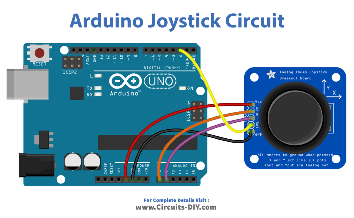
Wiring / Connections
| Arduino | Joystick |
|---|---|
| 5V | VCC |
| GND | GND |
| A4 | VRY |
| A5 | VRX |
| D2 | SW |
Installing Arduino IDE
First, you need to install Arduino IDE Software from its official website Arduino. Here is a simple step-by-step guide on “How to install Arduino IDE“.
Code
Now copy the following code and upload it to Arduino IDE Software.
#define VRX_PIN  A0 // Arduino pin connected to VRX pin
#define VRY_PIN  A1 // Arduino pin connected to VRY pin

int xValue = 0; // To store value of the X axis
int yValue = 0; // To store value of the Y axis

void setup() {
  Serial.begin(9600) ;
}

void loop() {
  // read analog X and Y analog values
  xValue = analogRead(VRX_PIN);
  yValue = analogRead(VRY_PIN);

  // print data to Serial Monitor on Arduino IDE
  Serial.print("x = ");
  Serial.print(xValue);
  Serial.print(", y = ");
  Serial.println(yValue);
  delay(200);
}
Working Explanation
First, the joystick module’s X and Y axes are connected to analog pins on the Arduino. Then, the Arduino reads the analog values from the joystick module and converts them into usable data for controlling other devices or performing desired actions.
This data can be displayed on the serial monitor for debugging and testing purposes. To do this, Arduino uses the built-in analogRead() function and the Serial.print() function. In the code, the analog values from the joystick module are read and stored in variables, and then these values are used to control various functions such as turning on and off an LED, controlling the speed of a motor, or adjusting the brightness of an LED. The code can be customized to suit different applications and requirements.
Applications
- Remote control of robots or other devices
- Control of LED matrix displays
- Video game controllers
- Joystick-controlled musical instruments
- Navigating menus in embedded systems
- Industrial control and automation
- HMI (Human-Machine Interface) systems.
Conclusion.
We hope you have found this Arduino – Joystick Circuit very useful. If you feel any difficulty in making it feel free to ask anything in the comment section.
Related posts:
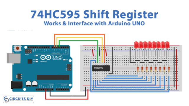 74HC595 Shift Register Works & Interface with Arduino UNO
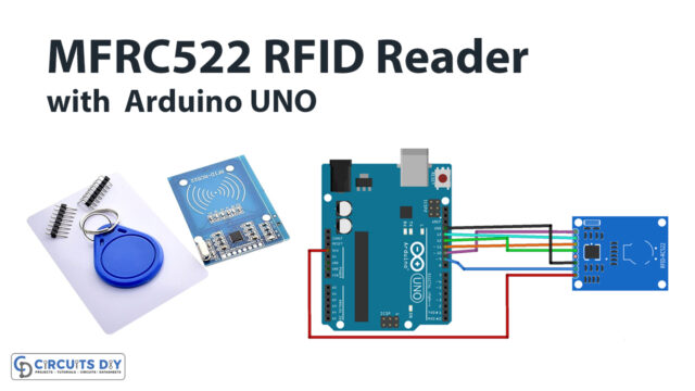 How to Interface MFRC522 RFID Reader with Arduino UNO
 DHT21 / AM2301 Temperature Humidity Sensor with Arduino
 WS2812B Addressable RGB LED Interfacing with Arduino
 Controlling DC, Stepper & Servo with L293D Motor Driver
 Soil Moisture Sensor - Arduino Tutorial