
Introduction
The ESP32 is a powerful microcontroller module that has gained immense popularity among electronics enthusiasts and IoT developers. It offers Wi-Fi and Bluetooth connectivity, a dual-core processor, and a wide range of GPIO pins, making it an ideal choice for a variety of projects. While there are many ESP32 breakout boards available in the market, building your own can be a rewarding experience. In this article, we will guide you through the process of creating your own ESP32 breakout board with the bare minimum components.
PCBWay commits to meeting the needs of its customers from different industries in terms of quality, delivery, cost-effectiveness, and any other demanding requests. As one of the most experienced PCB manufacturers in China. They pride themselves to be your best business partners as well as good friends in every aspect of your PCB needs.
What is ESP32 Breakout Board?
An ESP32 breakout board is a compact circuit board designed to provide easy access to the GPIO (General Purpose Input/Output) pins, power supply, and other features of the ESP32 microcontroller
Hardware Components
To make ESP32 Breakout Board, you’ll need the following hardware components to get started:
| S.no | Component | Value | Qty |
|---|---|---|---|
| 1. | ESP32 WiFi Chip | WROOM | 1 |
| 2. | AA Battery Cells | 1.5v | 2 |
| 3. | FTDI232 | Programmer | 1 |
| 4. | LED | Green Blue | 2 |
| 5. | Resistor | Ω | 1 |
| 6. | Breadboard | – | 1 |
| 7. | Jumper Wires | – | 1 |
Steps Making ESP32 Breakout Board
After gathering all the components above you will be required to make a PCB.
Design PCB
If you choose to design your own PCB, you can use software tools like Eagle, KiCad, or EasyEDA. Create a schematic for your breakout board, including the necessary connections for the ESP32 module, power supply, and any other components you plan to incorporate. Then, convert the schematic into a PCB layout, ensuring that it fits within the desired dimensions for your breakout board.
Schematic
Make connections according to the circuit diagram given below.
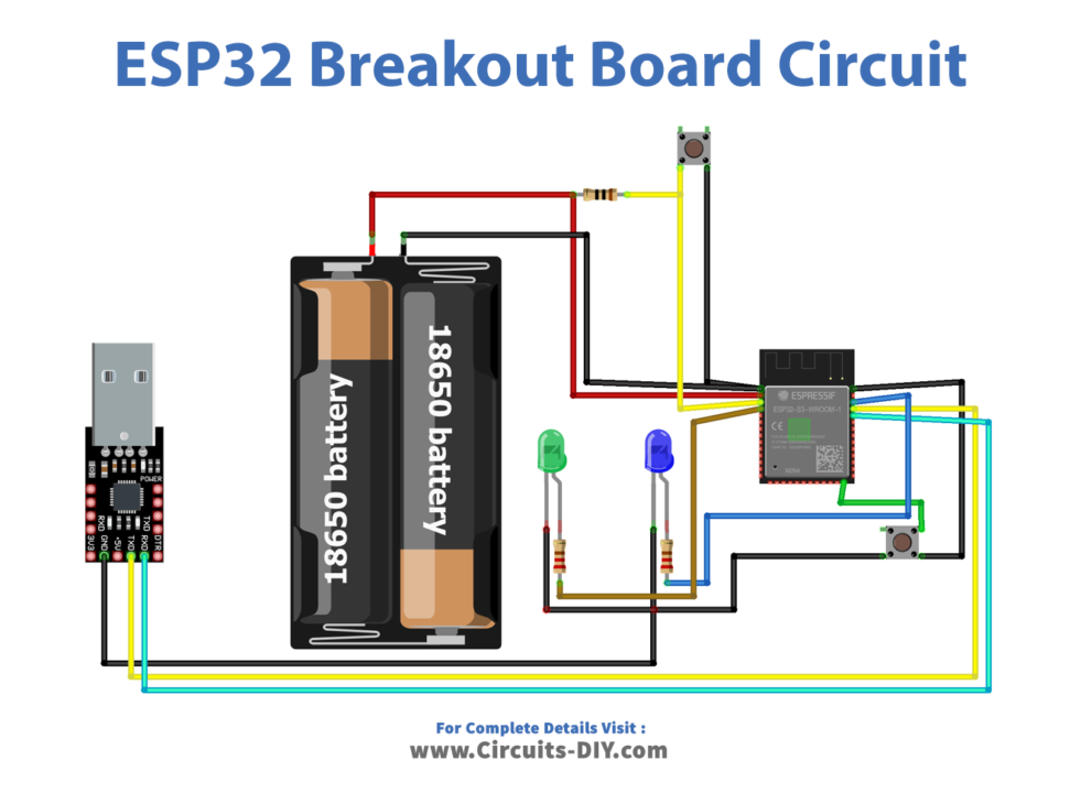
Wiring / Connections
| ESP32 Chip | Components |
|---|---|
| 3.3v VCC | Battery +ve 3.3v |
| GND | Battery Ground |
| GPIO2 | Green LED +ve |
| GPIO4 | Blue LED +ve |
Connect the USB-to-Serial Converter
To enable programming and debugging of the ESP32 module, connect the USB-to-Serial converter to the appropriate pins on your breakout board. Typically, you will need to connect the converter’s RXD, TXD, GND, and VCC pins to the corresponding pins on the ESP32 module. Refer to the datasheet or pinout diagram of your specific ESP32 module for the pin assignments.
Installing Arduino IDE
First, you need to Download Arduino IDE Software from its official website Arduino. Here is a simple step-by-step guide on “How to install Arduino IDE“.
Installing the ESP32 Board in Arduino IDE
After the Installation of Arduino IDE, There’s an add-on that allows you to program the ESP32 using the Arduino IDE. Here is a simple guide on “How to Install ESP32 on Arduino IDE“.
Code
Now copy the following code and upload it to Arduino IDE Software.
// Load Wi-Fi library
#include <WiFi.h>
// Replace with your network credentials
const char* ssid = "YOUR SSID";
const char* password = "YOUR PASSWORD";
// Set web server port number to 80
WiFiServer server(80);
// Variable to store the HTTP request
String header;
// Auxiliary variables to store the current output state
String output2State = "off";
String output4State = "off";
// Assign output variables to GPIO pins
const int output2 = 2;
const int output4 = 4;
// Current time
unsigned long currentTime = millis();
// Previous time
unsigned long previousTime = 0;
// Define timeout time in milliseconds (example: 2000ms = 2s)
const long timeoutTime = 2000;
void setup() {
  Serial.begin(115200);
  // Initialize the output variables as outputs
  pinMode(output2, OUTPUT);
  pinMode(output4, OUTPUT);
  // Set outputs to LOW
  digitalWrite(output2, LOW);
  digitalWrite(output4, LOW);
  // Connect to Wi-Fi network with SSID and password
  Serial.print("Connecting to ");
  Serial.println(ssid);
  WiFi.begin(ssid, password);
  while (WiFi.status() != WL_CONNECTED) {
    delay(500);
    Serial.print(".");
  }
  // Print local IP address and start web server
  Serial.println("");
  Serial.println("WiFi connected.");
  Serial.println("IP address: ");
  Serial.println(WiFi.localIP());
  server.begin();
}
void loop(){
  WiFiClient client = server.available();   // Listen for incoming clients
  if (client) {                             // If a new client connects,
    currentTime = millis();
    previousTime = currentTime;
    Serial.println("New Client.");          // print a message out in the serial port
    String currentLine = "";                // make a String to hold incoming data from the client
    while (client.connected() && currentTime - previousTime <= timeoutTime) {  // loop while the client's connected
      currentTime = millis();
      if (client.available()) {             // if there's bytes to read from the client,
        char c = client.read();             // read a byte, then
        Serial.write(c);                    // print it out the serial monitor
        header += c;
        if (c == '\n') {                    // if the byte is a newline character
          // if the current line is blank, you got two newline characters in a row.
          // that's the end of the client HTTP request, so send a response:
          if (currentLine.length() == 0) {
            // HTTP headers always start with a response code (e.g. HTTP/1.1 200 OK)
            // and a content-type so the client knows what's coming, then a blank line:
            client.println("HTTP/1.1 200 OK");
            client.println("Content-type:text/html");
            client.println("Connection: close");
            client.println();
            // turns the GPIOs on and off
            if (header.indexOf("GET /2/on") >= 0) {
              Serial.println("GPIO 2 on");
              output2State = "on";
              digitalWrite(output2, HIGH);
            } else if (header.indexOf("GET /2/off") >= 0) {
              Serial.println("GPIO 2 off");
              output2State = "off";
              digitalWrite(output2, LOW);
            } else if (header.indexOf("GET /4/on") >= 0) {
              Serial.println("GPIO 4 on");
              output4State = "on";
              digitalWrite(output4, HIGH);
            } else if (header.indexOf("GET /4/off") >= 0) {
              Serial.println("GPIO 4 off");
              output4State = "off";
              digitalWrite(output4, LOW);
            }
            // Display the HTML web page
            client.println("<!DOCTYPE html><html>");
            client.println("<head><meta name=\"viewport\" content=\"width=device-width, initial-scale=1\">");
            client.println("<link rel=\"icon\" href=\"data:,\">");
            // CSS to style the on/off buttons
            // Feel free to change the background-color and font-size attributes to fit your preferences
            client.println("<style>html { font-family: Helvetica; display: inline-block; margin: 0px auto; text-align: center;}");
            client.println(".button { background-color: #4CAF50; border: none; color: white; padding: 16px 40px;");
            client.println("text-decoration: none; font-size: 30px; margin: 2px; cursor: pointer;}");
            client.println(".button2 {background-color: #555555;}</style></head>");
            // Web Page Heading
            client.println("<body><h1>ESP32 Web Server</h1>");
            // Display current state, and ON/OFF buttons for GPIO 2
            client.println("<p>GPIO 2 - State " + output2State + "</p>");
            // If the output2State is off, it displays the ON button
            if (output2State=="off") {
              client.println("<p><a href=\"/2/on\"><button class=\"button\">ON</button></a></p>");
            } else {
              client.println("<p><a href=\"/2/off\"><button class=\"button button2\">OFF</button></a></p>");
            }
            // Display current state, and ON/OFF buttons for GPIO 4
            client.println("<p>GPIO 4 - State " + output4State + "</p>");
            // If the output4State is off, it displays the ON button
            if (output4State=="off") {
              client.println("<p><a href=\"/4/on\"><button class=\"button\">ON</button></a></p>");
            } else {
              client.println("<p><a href=\"/4/off\"><button class=\"button button2\">OFF</button></a></p>");
            }
            client.println("</body></html>");
            // The HTTP response ends with another blank line
            client.println();
            // Break out of the while loop
            break;
          } else { // if you got a newline, then clear currentLine
            currentLine = "";
          }
        } else if (c != '\r') {  // if you got anything else but a carriage return character,
          currentLine += c;      // add it to the end of the currentLine
        }
      }
    }
    // Clear the header variable
    header = "";
    // Close the connection
    client.stop();
    Serial.println("Client disconnected.");
    Serial.println("");
  }
}
Code Explanation
This code implements a basic ESP32 web server that allows control of GPIO pins through a Wi-Fi network. It sets up a server on port 80 and listens for client connections. When a client connects and sends an HTTP request, the code reads the request and checks for specific URLs to determine the desired action (turning GPIO pins on or off). It updates the GPIO pin states accordingly and generates an HTML web page as the response, displaying the current states and providing buttons to toggle them. The code loops to handle client requests and maintains the server connection until the client disconnects or a timeout occurs. Overall, it provides a straightforward example of remote GPIO control using the ESP32 breakout board.
Applications
- Internet of Things (IoT) projects
- Prototyping and development
- Sensor data acquisition
- Home automation and smart devices
- Robotics and automation
- Wearable technology
- Customized projects etc
Conclusion
The ESP32 breakout board is a valuable tool for makers, hobbyists, and engineers working with the ESP32 microcontroller. It simplifies the process of prototyping, development, and experimentation, providing easy access to GPIO pins and other essential features. The breakout board’s versatility and compatibility with various applications make it suitable for a wide range of projects, including IoT, home automation, robotics, wearable technology, and more. With its built-in Wi-Fi and Bluetooth capabilities.


Good post! We are linking to this particularly great content on our site.
Keep up the good writing.